


26
C l i m a t e M a s t e r W a t e r- S o u r c e H e a t P u m p s
C L I M A T E M A S T E R W A T E R - S O U R C E H E A T P U M P S
Tr a n q u i l i t y
®
2 2 ( T Z ) S e r i e s
R e v i s e d : 0 1 / 2 1 / 1 3
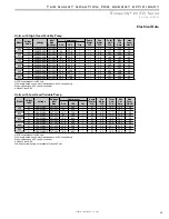
Electrical - Power & Low Voltage Wiring
CAUTION!
Use only copper conductors for
fi
eld installed
electrical wiring. Unit terminals are not designed to accept
other types of conductors.
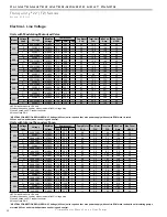
Electrical - Line Voltage
- All fi eld installed wiring,
including electrical ground, must comply with the National
Electrical Code as well as all applicable local codes. Refer
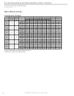
to the unit electrical data for fuse sizes. Consult wiring
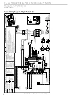
diagram for fi eld connections that must be made by
the installing (or electrical) contractor. All fi nal electrical
connections must be made with a length of fl exible conduit
to minimize vibration and sound transmission to the
building.
General Line Voltage Wiring
- Be sure the available
power is the same voltage and phase shown on the unit
serial plate. Line and low voltage wiring must be done in
accordance with local codes or the National Electric Code,
whichever is applicable.
WARNING!
Disconnect electrical power source to prevent
injury or death from electrical shock.
CAUTION!
WARNING!
Power Connection -
Line voltage connection is made
by connecting the incoming line voltage wires to the “L”
side of the contractor as shown in the unit wiring diagram.
Consult electrical data tables for correct fuse size.
460 volt units require a neutral wire.
Transformer -
All 208/230 voltage units are factory wired
for 208 volt. If supply voltage is 230 volt, installer must
rewire transformer. See wire diagram for connections.
ELECTRICAL - LOW VOLTAGE WIRING
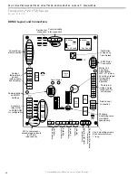
Thermostat Connections
- The thermostat will be wired
to the DXM2 board located within the unit control box.
Refer to the unit wiring diagram for specifi c details.
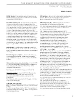
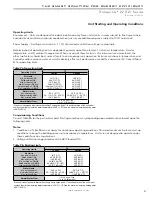
Low Water Temperature Cutout Selection
- The DXM2
control allows the fi eld selection of low water (or water-
antifreeze solution) temperature limit by clipping jumper
JW3, which changes the sensing temperature associated
with thermistor LT1. Note that the LT1 thermistor is
located on the refrigerant line between the coaxial heat
exchanger and expansion device (TXV). Therefore, LT1 is
sensing refrigerant temperature, not water temperature,
which is a better indication of how water fl ow rate/
temperature is affecting the refrigeration circuit.
The factory setting for LT1 is for systems using water
(30°F [-1.1°C] refrigerant temperature). In low water
temperature (extended range) applications with
antifreeze (most ground loops), jumper JW3 should be
clipped as shown in Figure 17 to change the setting to
10°F [-12.2°C] refrigerant temperature, a more suitable
temperature when using an antifreeze solution. All
ClimateMaster units operating with entering water
temperatures below 60°F [15.6°C] must include the
optional water/refrigerant circuit insulation package to
prevent internal condensation.