


41
c l i m a t e m a s t e r. c o m
Tranquility
®
30 Digital (TE) Series IOM - 60Hz HFC-410A
R e v. : 2 9 M a y, 2 0 1 5 J
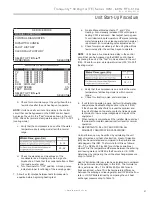
Unit Start-Up Procedure
SERVICE MODE
MANUAL OPERATION
CONTROL DIAGNOSTICS
DIPSWITCH CONFIG
FAULT HISTORY
CLEAR FAULT HISTORY
SELECT OPTION
PREVIOUS SELECT
MANUAL OPERATING MODE
Y1
COMM OUTPUT
OFF
Y2
COMM OUTPUT
OFF
W
COMM OUTPUT
OFF
O
COMM OUTPUT
OFF
G
COMM OUTPUT
OFF
H
COMM OUTPUT
OFF
DH
COMM OUTPUT
OFF
ECM
AIRFLOW
0
PUMP SPEED
0%
TEST MODE
OFF
SELECT OPTION
PREVIOUS SELECT
9 - 12
20 - 26
4 - 8
10 - 17
b. Check for cool air delivery at the unit grille within a
few minutes after the unit has begun to operate.
NOTE
:
Units have a
fi
ve minute time delay in the control
circuit that can be bypassed on the DXM2 control board
by placing the unit in the “Test” mode as shown in the unit
IOM. Check for normal air temperature drop of 15°F to 25°F
(cooling mode).
c. Verify that the compressor is on and that the water
temperature rise (cooling mode) is within normal
range.
d. Check the elevation and cleanliness of the
condensate lines. Dripping may be a sign of a
blocked line. Check that the condensate trap is
fi
lled
to provide a water seal.
e. Turn thermostat to “OFF” position. A hissing noise
indicates proper functioning of the reversing valve.
7. Allow
fi
ve (5) minutes between tests for pressure to
equalize before beginning heating test.
a. Go into Manual Mode activate Y1, and Y2 for
Heating. Also manually increase CFM until desired
heating CFM is achieved. Next adjust pump speed
% until desired loop temperature di
ff
erence (entering
water temperature minus leaving water temperature)
is achieved. (For modulating valve adjust valve %).
b. Check for warm air delivery at the unit grille within a
few minutes after the unit has begun to operate.
NOTE
: Units have a
fi
ve minute time delay in the control
circuit that can be bypassed on the DXM2 control board
by placing the unit in the “Test” mode as shown in the unit
IOM. Check for normal air temperature rise of 20°F to 30°F
(heating mode).
c. Verify that the compressor is on and that the water
temperature fall (heating mode) is within normal
range.
e. Check for vibration, noise, and water leaks.
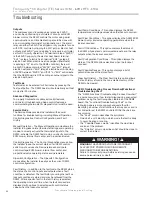
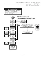
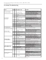
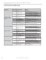
8. If unit fails to operate properly, perform troubleshooting
analysis (see troubleshooting section in the unit IOM).
If the check described fails to reveal the problem and
the unit still does not operate, contact a trained service
technician to insure proper diagnosis and repair of the
equipment.
9. When testing is complete, exit the Installer Menu and set
thermostat to maintain desired comfort level for normal
operation.
10. BE CERTAIN TO FILL OUT AND RETURN ALL
WARRANTY REGISTRATION PAPERWORK.
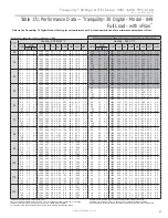
Unit performance may be veri
fi
ed by calculating the unit
heat of rejection and heat of extraction. Heat of Rejection
(HR) can be calculated and compared to the performance
data pages in this IOM. The formula for HR is as follows:
HR = TD x GPM x 500 (or 485 for anti-freeze solutions),
where TD is the temperature di
ff
erence between the entering
and leaving water, and GPM is the
fl
ow rate in U.S. GPM
determined by comparing the unit heat exchanger pressure
drop to Table 13.
Heat of Extraction (HE) can also be calculated and compared
to the performance data pages in this IOM. The formula for
HE is as follows: HE = TD x GPM x 500 (or 485 for anti-
freeze solutions), where TD is the temperature di
ff
erence
between the entering and leaving water, and GPM is the
fl
ow
rate in U.S. GPM determined by comparing the unit heat
exchanger pressure drop to Table 13.


