


37
c l i m a t e m a s t e r. c o m
Tranquility
®
30 Digital (TE) Series IOM - 60Hz HFC-410A
R e v. : 2 9 M a y, 2 0 1 5 J
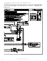
DXM2 Controls
CAUTION!
CAUTION!
Do not restart units without inspection and
remedy of faulting condition. Equipment damage may occur.
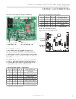
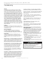
Figure 30: Test Mode Button
(240Vac)
Com
N.O.
Fan Enable
Test
P5
B-
Gnd
P4
A+ 24V
(240Vac)
Fan Speed
N.O.
N.C.
12V
OUT
Gnd
P8
IN
NC
P12
Pust test button to
enter Test Mode and
speed-up timing and
delays for 20 minutes.
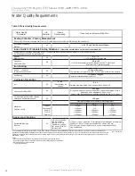
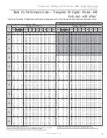
Conventional
T-stat signal
(Non-Communicating)
Unit
ECM fan
G
Fan only
G, Y1
Stage 1 heating
1
G, Y1, Y2
Stage 2 heating
1
G, Y1, Y2, W
Stage 3 heating
1
G, W
Emergency heat
G, Y1, O
Stage 1 cooling
2
G, Y1, Y2, O
Stage 2 cooling
2
1 Stage 1 = 1st stage compressor, 1st stage fan operation
Stage 2 = 2nd stage compressor, 2nd stage fan operation
Stage 3 = 2nd stage compressor, auxiliary electric heat, 3rd
stage fan operation
2 Stage 1 = 1st stage compressor, 1st stage fan operation,
reversing
valve
Stage 2 = 2nd stage compressor, 2nd stage fan operation,
reversing
valve
DXM2 iGate
™
Controller
DXM2 is the next generation in
controls and is capable of 2-way communication with smart
components, like the communicating iGate
™
thermostat,
ECM fan motor, Magna Variable-Speed Pump and
con
fi
guration/diagnostic tool.
For most residential applications, con
fi
guration, monitoring and
diagnostics can all be done from the thermostat/ service tool
so there’s no need to read LEDs and change DIP switches.
For details on user settings, refer to iGate
™
Communicating
Thermostat User Manual (part # 97B0055N02).
For details on Installer settings (not to be used by
consumers), refer to iGate
™
Communicating Thermostat
Installer manual (part # 97B0055N03).
For details on installer/service settings on the iGate
™
con
fi
guration/diagnostic tool, refer to operation manual (part
# 97B0106N01).
For further details on the DXM2 control, refer to the DXM2
Application, Operation and Maintenance Manual (part #
97B0003N15). The DXM2 AOM is shipped with each unit.
Thermostat compatibility
It is strongly recommended that iGate
™
communicating
thermostat (ATC32U**) or iGate
™
con
fi
guration/ diagnostic
tool (ACDU**) be used with DXM2 control, to ensure easy
con
fi
guration, monitoring and diagnostics, in PLAIN English.
For example, Air
fl
ow CAN NOT be con
fi
gured without either
the communicating thermostat or con
fi
guration/ diagnostic
tool
Field Hardware Confi guration Options
- Note: In the
following
fi
eld hardware con
fi
guration options, changes
should be made ONLY when power is removed from the
DXM2 control.
Water coil low temperature limit setting:
Jumper 3 (JW3-
LT1 Low Temp) provides
fi
eld selection of temperature limit
setting for LT1 of 30°F or 10°F [-1°F or -12°C] (refrigerant
temperature).
Not Clipped = 30°F [-1°C]. Clipped = 10°F [-12°C].
A0-2: Confi gure Modulating Valve or Variable-Speed
Pump (Internal water fl ow Models Only)
A0-2 jumper (Figure 32) Factory Set to “IOV” if using Internal
Modulating Motorized Valve or “PMW” if using Internal
Variable-Speed Pump. This applies only to units with Internal
Water Flow Control.
DIP Switches – There’s no need to change the DIP switches
settings on Residential units. All DIP switches in S1 and S2
should be “on”. In S3, S3-1 should be “on” and the rest should
be “o
ff
”. For more details on DIP switches, refer to the DXM2
AOM (part # 97B0003N15).
DXM2 Control Start-up Operation
The control will not operate until all inputs and safety controls
are checked for normal conditions. The compressor will have a
5 minute anti-short cycle delay at power-up. The
fi
rst time after
power-up that there is a call for compressor, the compressor
will follow a 5 to 80 second random start delay.
After the random start delay and anti-short cycle delay,
the compressor relay will be energized. On all subsequent
compressor calls, the random start delay is omitted.
Test Mode Button
Test mode allows the service technician to check the operation
of the control in a timely manner. By momentarily pressing the
TEST push button, the DXM2 control enters a 20 minute test
mode period in which all time delays are sped up 15 times.
Table 11: Unit Operation


