


R e s i d e n t i a l Tr a n q u i l i t y
®
2 7 S p l i t ( T T S ) - 6 0 H z H F C - 4 1 0 A
R e v. : 8 M a y, 2 0 1 4 C
c l i m a t e m a s t e r. c o m
9
Installation
The installation of water source heat pump units and all
associated components, parts and accessories which make
up the installation shall be in accordance with the regulations
of ALL authorities having jurisdiction and MUST conform to
all applicable codes. It is the responsibility of the installing
contractor to determine and comply with ALL applicable
codes and regulations.
Removing Existing Condensing Unit (Where Applicable)
1. Pump down condensing unit. Close the liquid line
service valve of existing condensing unit and start
compressor to pump refrigerant back into compressor
section. Then, close suction service valve while
compressor is still running to trap refrigerant in
compressor section. Immediately kill power to the
condensing unit.
2. Disconnect power and low voltage and remove old
condensing unit. Cut or unbraze line set from unit.
Remove condensing unit.
3. If condensing unit is not operational or will not pump
down, refrigerant should be recovered using appropriate
equipment.
4. Replace line set, especially if upgrading system from
R-22 to HFC-410A refrigerant. If line set cannot be
replaced, it must be thoroughly
fl
ushed before installing
new compressor section. HFC-410A compressors use
POE oil instead of mineral oil (R-22 systems). Mineral oil
is not compatible with POE oil, and could cause system
damage if not completely
fl
ushed from the line set.
Unit Location
The TTS unit is not designed for outdoor installation. Locate
the unit in an INDOOR area that allows enough space for
service personnel to perform typical maintenance or repairs
without removing unit. Units are typically installed in a
mechanical room or closet. Never install units in areas subject
to freezing or where humidity levels could cause cabinet
condensation (such as unconditioned spaces subject to
100% outside air). Consideration should be given to access
for easy removal of service access panels. Provide su
ffi
cient
room to make water, electrical, and line set connections.
Any access panel screws that would be di
ffi
cult to remove
after the unit is installed should be removed prior to setting
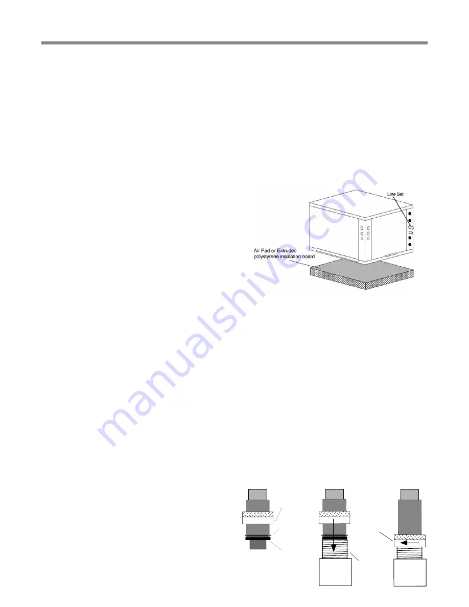
the unit. Refer to Figure 2 for an illustration of a typical
installation. Refer to “Physical Dimensions” section for
dimensional data. Conform to the following guidelines when
selecting unit location:
1. Install the unit on a piece of rubber, neoprene or other
mounting pad material for sound isolation. The pad should
be at least 3/8” [10mm] to 1/2” [13mm] in thickness.
Extend the pad beyond all four edges of the unit.
2. Provide adequate clearance for maintenance and
service. Do not block access panels with piping, conduit
or other materials.
3. Provide access for servicing the compressor and coils
without removing the unit.
4. Provide an unobstructed path to the unit within the
closet or mechanical room. Space should be su
ffi
cient to
allow removal of the unit, if necessary.
5. Provide access to water valves and
fi
ttings and
screwdriver access to the unit side panels and all
electrical connections.
Air Handler Installation
This manual speci
fi
cally addresses the compressor section
of the system. Air handler location and installation should
be according to the instructions provided with the air
handling unit.
Water Connections
The TTS models utilize swivel piping
fi
ttings for water
connections that are rated for 450 psi (3101 kPa) operating
pressure. The connections have a rubber gasket seal similar
to a garden hose gasket, which when mated to the
fl
ush
end of most 1” threaded male pipe
fi
ttings provides a leak-
free seal without the need for thread sealing tape or joint
compound. Check for burrs and ensure that the rubber seal
is in the swivel connector prior to attempting any connection
(rubber seals are shipped attached to the swivel connector).
DO NOT OVER TIGHTEN or leaks may occur.
The female locking ring is threaded onto the pipe threads
which holds the male pipe end against the rubber gasket,
and seals the joint. HAND TIGHTEN ONLY! DO NOT
OVERTIGHTEN!
Gasket
Swivel Nut
Stainless steel
snap ring
Brass Adaptor
Hand Tighten
Only!
Do Not
Overtighten!
External Flow Controller Mounting
The Flow Controller can be mounted beside the unit as
shown in Figure 7. Review the Flow Controller installation
manual for more details.
Figure 2: TTS Installation
Figure 4: Water Connections


