background image

T H E   S M A R T   S O L U T I O N   F O R   E N E R G Y   E F F I C I E N C Y

T (ERV) Series

R e v. :   1 5   A p r i l ,   2 0 1 6

5

c l i m a t e m a s t e r. c o m

lowest tension at which the belt will not slip under peak 

load conditions.
1.  Disconnect main power to unit before making 

adjustment to economizer and/or ERV unit.

2.  Replace ERV control access cover.
3.  Set thermostat to normal operating position.
4.  Restore power to unit.

Maintenance

1.   All motors use pre-lubricated sealed bearings; no 

further lubrication is necessary.

2.   Make visual inspection of motors, belts and wheel 

rotating bearings during routine maintenance.

3.   Eight pie-shaped segments, are seated on stops 

between the segment retainer which pivots on the 

wheel rim and secured to the hub and rim of wheel. 

Annual inspection of the self cleaning wheel is 

recommended. With power disconnected, remove 

ERV access panels (rear) and unplug [J150 & P150] 

(Refer to wiring  diagram in this instruction 

manual)

. Remove segment and wash with water and/

or mild detergent.

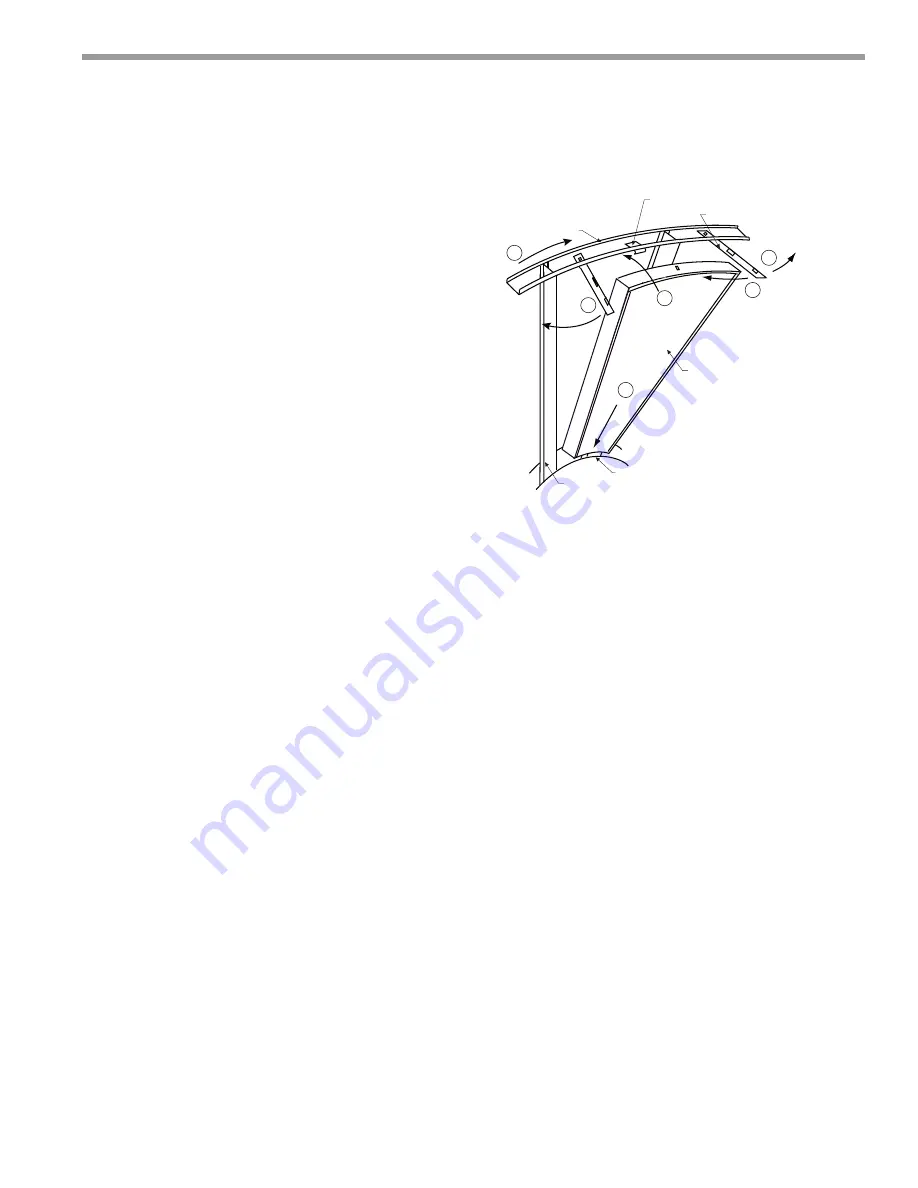
4.   To install wheel segments follow steps A through 

E . 

See Figure 1. 

Reverse procedure for segment 

removal.

A. Unlock two segment retainers (one on each side of 

the selected segment opening.

B. With the embedded stiffener facing the motor side, 

insert the nose of the segment between the hub 

plates.

C. Holding segment by the two outer corners, press 

the segment towards the center of the wheel 

and inwards against the spoke flanges. If hand 

pressure does not fully seat the segment, insert 

the flat tip of a screw driver between the wheel 

rim and outer corners of the segment and apply 

downward force while guiding the segment into 

place.

D. Close and latch each segment retainer under 

segment retaining catch.

E. Slowly rotate the wheel 180º. Install the second 

segment opposite the first for counterbalance. 

Rotate the two installed segments 90º  to balance 

the wheel while the third segment is installed. 

Rotate the wheel 180º again to install the fourth 

segment opposite the third. Repeat this sequence 

with the remaining four segments.

Pulley Kit Installation

The units are shipped from the factory at the low static 

setting. Pulley kits are available for the medium and high 

static settings. To install a pulley kit.
1.   Check content of pulley kit, if pulley kit contains:

a. An adjustable sheave and a fixed pitch pulley then 

remove belt and both motor and blower pulley

b. An adjustable sheave then remove the motor 

pulley.

c. A fixed pitch pulley then remove the blower pulley.

2.  Replace pulley(s) with the pulley(s) from pulley kit. 

Make sure each pulley is installed with a key. Tighten 

the set screw on the pulley(s) to 100 in.lb.

3.   Install the belt that came with the pulley kit. Tension 

belt as explained in the blower speed adjustment 

section.

4.   Check the speed of the blower. Adjust the motor 

sheave to increase or decrease the speed of the 

blower. See blower adjustment section.

B

C

A

D

E

D

HUB

SEGMENT

SPOKE

SEGMENT RETAINER CATCH

WHEEL RIM

SEGMENT RETAINER

Figure 1

Summary of Contents for TB SERIES

Page 1: ...e work In winter the ERV adsorbs heat and moisture from the exhaust air stream during one half of a complete rotation and gives them back to the cold drier intake air supply during the other half rota...

Page 2: ...CL IM ATEM ASTER WATER SOURCE HEAT PUMPS T ERV Series Rev 15 April 2016 2 ClimateMaster Water Source Heat Pumps This Page Intentionally Left Blank...

Page 3: ...M for CFM and external static pressure requirements See charts in this instruction Multiple pulley arrangements are available to meet the entire range 10 Replace access panel onto the ERV unit and sec...

Page 4: ...ff to avoid depressurization should be considered Recovery Wheel Mode On a thermostat call for blower operation in heating cooling or continuous blower the ERW will rotate between fresh air and exhaus...

Page 5: ...s against the spoke flanges If hand pressure does not fully seat the segment insert the flat tip of a screw driver between the wheel rim and outer corners of the segment and apply downward force while...

Page 6: ...erate properly without balancing damper 4 See blower performance charts for airflow at various E S P 5 Filter rack with 2 pleated filters included A B C D D E I G H F H ERV Data Dimensional Data ERV S...

Page 7: ...Jack Cycle Optional J48 Jack Control Box Fresh Air J50 Jack Control Box Wheel J51 Jack Control Box Exhaust Air J56 Jack Control Box Damper J148 Jack Fresh Air Motor Harness J150 Jack Wheel Motor Harn...

Page 8: ...sh Air J50 Jack Control Box Wheel J51 Jack Control Box Exhaust Air J56 Jack Control Box Damper J148 Jack Fresh Air Motor Harness J150 Jack Wheel Motor Harness J151 Jack Exhaust Air Motor Harness J152...

Page 9: ...t 208 230V 1 PH ERV UNIT WIRING DIAGRAM Notes 1 Remove jumper to install field optional low ambient switch 2 Selective voltage terminals for proper unit voltage 3 Optional low ambient switch 4 Optiona...

Page 10: ...V UNIT WIRING DIAGRAM Notes 1 Remove jumper to install field optional low ambient switch 2 Step down transformer assembly for 460 575 volt units 3 Selective voltage terminals for proper unit voltage 4...

Page 11: ...tor Filter in Intake Hood 2HP External Static Pressure in water 0 0 25 0 5 0 75 1 1 25 1 5 CFM 1200 1100 1225 1315 1405 1440 1695 1725 1400 1220 1275 1400 1480 1620 1730 1790 1600 1225 1345 1475 1615...

Page 12: ...ist Eliminator Filter in Intake Hood 3HP External Static Pressure in water 0 0 25 0 5 0 75 1 1 25 1 5 CFM 2000 820 930 1015 1095 1160 1245 1315 2400 920 1010 1090 1155 1240 1305 1405 2800 1000 1085 11...

Page 13: ...MF Mist Eliminator Filter in Intake Hood 5HP External Static Pressure in water 0 0 25 0 5 0 75 1 1 25 1 5 CFM 4600 820 910 990 1020 1135 1165 1225 5000 885 965 1040 1100 1160 1225 1280 5400 910 1000 1...

Page 14: ...or incorrect system design or the improper application of CM s products CM is not responsible for 1 The costs of any uids refrigerant or other system components or associated labor to repair or replac...

Page 15: ...THE SMART SOLUTION FOR ENERGY EFFIC I E NC Y T ERV Series Rev 1 5 A pri l 2 0 1 6 15 climatemaster com Notes...

Page 16: ...ment at 1 405 745 6000 for specific information on the current design and specifications Statements and other information contained herein are not express warranties and do not form the basis of any b...

Reviews: