background image

Preface

VI

Preface

4.

Avoid interference.

 Keep the computer away from high capacity transformers, electric motors, and other strong mag-

netic fields. These can hinder proper performance and damage your data.

5.

Take care when using peripheral devices

.

Power Safety

The computer has specific power requirements:

Only use a power adapter approved for use with this computer.

Your AC adapter may be designed for international travel but it still requires a steady, uninterrupted power supply. If you are 
unsure of your local power specifications, consult your service representative or local power company.

The power adapter may have either a 2-prong or a 3-prong grounded plug. The third prong is an important safety feature; do 
not defeat its purpose. If you do not have access to a compatible outlet, have a qualified electrician install one.

When you want to unplug the power cord, be sure to disconnect it by the plug head, not by its wire.

Make sure the socket and any extension cord(s) you use can support the total current load of all the connected devices.

Before cleaning the computer, make sure it is disconnected from any external power supplies.

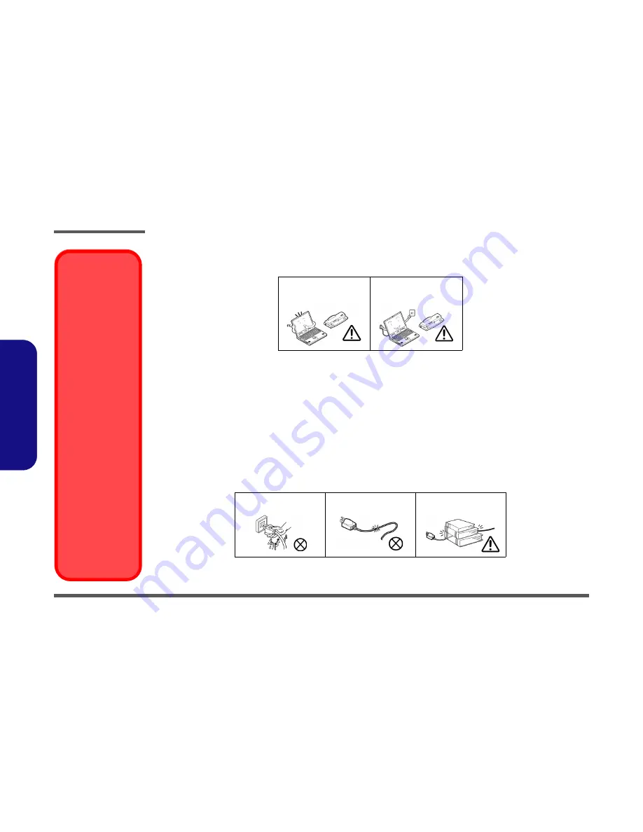
Use only approved brands of 
peripherals.

Unplug the power cord before 
attaching peripheral devices.

Do not plug in the power 
cord if you are wet.

Do not use the power cord if 
it is broken.

Do not place heavy objects 
on the power cord.

Removal Warning

When removing any
cover(s) and screw(s)
for the purposes of de-
vice upgrade, remem-
ber to replace the
cover(s) and screw(s)
before restoring power
to the system.

Also note the following
when the cover is re-
moved:

Hazardous mov-
ing parts.

Keep away from 
moving fan blades

Power Safety 

Warning

Before you undertake
any upgrade proce-
dures, make sure that
you have turned off the
power, and discon-
nected all peripherals
and cables (including
telephone lines and
power cord). You must
also remove your bat-
tery in order to prevent
accidentally turning the
machine on.

Summary of Contents for XMG-U505

Page 1: ......

Page 2: ... down properly and don t forget to save your work Remember to periodically save your data as data may be lost if the battery is depleted Do not expose the computer to any shock or vibration Do not place it on an unstable surface Do not place anything heavy on the computer Do not expose it to excessive heat or direct sunlight Do not leave it in a place where foreign matter or mois ture may affect t...

Page 3: ...be sure to disconnect it by the plug head not by its wire Make sure the socket and any extension cord s you use can support the total current load of all the connected devices Before cleaning the computer make sure it is disconnected from any external power supplies Use only approved brands of peripherals Unplug the power cord before attaching peripheral devices Do not plug in the power cord if yo...

Page 4: ...ur hands or metal objects Battery Guidelines The following can also apply to any backup batteries you may have If you do not use the battery for an extended period then remove the battery from the computer for storage Before removing the battery for storage charge it to 60 70 Check stored batteries at least every 3 months and charge them to 60 70 Battery Disposal The product that you have purchase...

Page 5: ...the computer e g keyboard and mouse to their ports 5 Attach the AC DC adapter to the DC In jack at the rear of the computer then plug the AC power cord into an outlet and connect the AC power cord to the AC DC adapter make sure you use the adapter when first setting up the computer as to safe guard the computer during shipping the battery will be locked to not power the system until first con nect...

Page 6: ...Adapter Options NVIDIA GeForce GTX 980M PCIe Video Card 8GB GDDR5 Video RAM on board Microsoft DirectX 12 Compatible NVIDIA GeForce GTX 970M PCIe Video Card 6GB GDDR5 Video RAM Microsoft DirectX 12 Compatible NVIDIA GeForce GTX 965M PCIe Video Card 4GB GDDR5 Video RAM Microsoft DirectX 12 Compatible Memory Four 204 Pin SO DIMM Sockets Supporting DDR3L 1600MHz Memory The real memory operating frequ...

Page 7: ...y Option Slot 3 for 3G 4G Module Communication Built In Gigabit Ethernet LAN 2 0M FHD PC Camera Module Factory Option M 2 3G 4G Module WLAN Bluetooth M 2 Modules Factory Option Intel Wireless AC 7265 Wireless LAN 802 11ac Bluetooth 4 0 Factory Option Intel Wireless N 7265 Wireless LAN 802 11b g n Bluetooth 4 0 Factory Option Intel Wireless AC 3160 Wireless LAN 802 11ac Bluetooth 4 0 Factory Option...

Page 8: ...oduction External Locator Top View with LCD Panel Open Figure 1 Top View 1 Built In PC Camera 2 PC Camera LED 3 Built In Microphone 4 LCD 5 Speakers 6 Power Button 7 LED Indicators 8 Keyboard 9 TouchPad and Buttons 10 Fingerprint Reader Optional 2 1 7 8 7 6 5 4 5 3 9 10 ...

Page 9: ...roduction External Locator Front Right side Views Figure 2 Front Views 1 Light Bar 2 LED Power Indicators Figure 3 Right Side Views 1 USB 3 0 Port 2 S PDIF Out Jack 3 Headphone Jack 4 Microphone Jack 5 Line In Jack 6 Security Lock Slot 2 Front 1 Right 1 2 3 4 5 6 ...

Page 10: ... Locator Left Side Rear View Figure 4 Left Side View 1 RJ 45 LAN Jack 2 USB 3 0 Port 3 USB 3 1 Ports 4 Multi in 1 Card Reader 5 Combined eSATA Powered USB 3 0 Port 5 1 2 3 Left 4 3 Figure 5 Rear View 1 Vent Fan Intake 2 HDMI Out Port 3 Display Ports 4 DC In Jack Rear 4 1 2 3 1 3 ...

Page 11: ...oduction External Locator Bottom View Figure 6 Bottom View 1 Vent 2 Component Bay Cover 3 Battery 4 HDD Bay Overheating To prevent your com puter from overheating make sure nothing blocks the vent fan in takes while the com puter is in use 3 2 1 4 1 1 1 ...

Page 12: ...c ing the connection make sure the connector is oriented in the same way The pin1 side is usually not indicated Pressure sockets for multi wire connectors To release this connector type grasp it at its head and gently rock it from side to side as you pull it out Do not pull on the wires themselves When replacing the connection do not try to force it The socket only fits one way Pressure sockets fo...

Page 13: ...o not pull on the wire 6 Peripherals Turn off and detach any peripherals 7 Beware of static discharge ICs such as the CPU and main support chips are vulnerable to static electricity Before handling any part in the computer discharge any static electricity inside the computer When handling a printed circuit board do not use gloves or other materials which allow static electricity buildup We suggest...

Page 14: ...Figure 1a 3 Slide the latch in the direction of the arrow and hold it in place Figure 1a 4 Lift the battery in the direction of the arrow 5 Lift the battery out of the compartment Figure 1c 4 Battery 1 2 3 6 4 a b 1 2 4 3 c Figure 1 Battery Removal a Slide the latch and hold in place b Lift the battery up toward the direction of the arrow c Lift the battery out ...

Page 15: ...he hard disk bay cover and remove screws Figure 2a 3 Remove the hard disk bay cover by sliding the cover at point Figure 2b Figure 2 HDD Assembly Removal a Locate the HDD bay cover and remove the screws b Remove the hard disk bay cover by sliding the cover at point 3 2 Screws 1 2 3 HDD System Warning New HDD s are blank Before you begin make sure You have backed up any data you want to keep from y...

Page 16: ... cover from the hard disk Figure 3f 8 Reverse the process to install a new hard disk do not forget to replace all the screws and covers 6 4 5 6 6 7 6 8 9 12 13 14 c d 8 4 7 e 13 5 HDD 2 HDD 1 6 4 9 14 f 12 10 11 4 HDD Bay Cover 6 HDD 2 Assembly 8 HDD 1 Assembly 13 Adhesive Cover 14 HDD 4 Screws Figure 3 HDD Assembly Removal cont d c Remove the HDD bay cover d Lift and pull the HDD 2 assembly in th...

Page 17: ...the following pages are all 9 5mm H hard disk drives In some cases 7mm H hard disk drives will be installed Figure 4 Foam Rubber Insert for 7mm H HDDs If you are replacing a 9 5mm H HDD with a 7mm H HDD then insert the foam rubber insert If you are replacing a 7mm H HDD with a 9 5mm H HDD then remove the foam rub ber insert HDD 2 HDD 1 ...

Page 18: ...screw from the SSD Figure 5a 3 The SSD module will pop up Figure 5b 4 Lift the SSD module up and off the computer Figure 5c 5 Reverse the process to install a new SSD make sure that the hexagonal screw is in the correct location depending upon the size of the module 2 SSD Module 1 Screw Figure 5 M 2 SSD Module Removal a Remove the screws b The SSD module will pop up c Lift the SSD module out 1 6 2...

Page 19: ...r the bottom case cover and two secondary memory sockets are located under the keyboard not user upgradable If you are installing only two RAM modules then they should be installed in the primary memory sockets under the component bay cover Note that the RAM located under the keyboard is not user upgradable Memory Upgrade Process 1 Turn off the computer and turn it over remove the battery page 2 5...

Page 20: ...ORCE the module it should fit without much pressure 10 Press the module in and down towards the mainboard until the slot levers click into place to secure the module 11 Replace the bay cover and screws 12 Restart the computer to allow the BIOS to register the new memory configuration as it starts up 6 6 7 Figure 7 RAM Module Removal cont d c Lift the component bay cover off the computer case The m...

Page 21: ...rimary memory sockets under the component bay cover Memory Upgrade Process 1 Turn off the computer and turn it over remove the battery page 2 5 2 Remove screws and component bay cover Figure 8a 3 Remove screws from the bottom of the computer Figure 8b 4 Open it up with the LCD on a flat surface before pressing at point to release the keyboard module use an eject stick to do this with a diameter no...

Page 22: ... fit one way Make sure the module is seated as far into the slot as it will go DO NOT FORCE the module it should fit without much pressure 13 Press the module in and down towards the mainboard until the slot levers click into place to secure the module 14 Replace the bay cover and screws 15 Restart the computer to allow the BIOS to register the new memory configuration as it starts up 11 12 14 12 ...

Page 23: ... Carefully disconnect cables then remove screw from the module socket Figure 13b 4 The Wireless LAN module will pop up Figure 13c 5 Lift the Wireless LAN module Figure 13d up and off the computer Figure 13 Wireless LAN Module Removal a The Wireless LAN mod ule will be visible at point under the keyboard b Disconnect the cables and remove the screw c The WLAN module will pop up d Lift the WLAN modu...

Page 24: ...les covers each cable will have either a black or transparent cable cover are color coded for iden tification as outlined in the table below Cable 1 is usually connected to antenna 1 Main on the module and cable 2 to antenna 2 Aux Module Type Antenna Type Cable Color Cable Cover Type WLAN WLAN Bluetooth Combo WM 1 Black Transparent WM 2 Gray WM 3 White LTE Broadband LTE 1 Black Black LTE 2 Gray 3G...

Page 25: ...y remove the screw from the module Figure 14b 4 The MSATA module will pop up Figure 14c 5 Lift the MSATA module up and off the computer Figure 14d 6 Reverse the process to install a new SSD make sure that the hexagonal screw is in the correct location Figure 14 M 2 SATA Module Removal a Locate the module b Remove the screw c The module will pop up d Lift the module up off the socket 1 2 6 3 6 3 4 ...

Reviews: