background image

Schematic  Diagrams

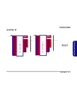
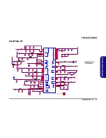
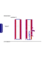
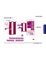
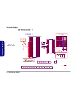
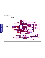
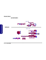
CARD READER(JMB261)  B - 23

B.Sch

e

m

a

tic D

iag
rams

CARD READER(JMB261)


3 . 3 V

3 . 3 V

3 . 3 V

D V D D

D V D D

V C C _ C A R D

3 . 3 V S

3 . 3 V

V C C _ C A R D

V C C _ C A R D

V C C _C A R D

V C C _ C A R D

V C C _ C A R D

3 . 3 V

3 . 3 V

3 . 3 V

3 . 3 V

3 . 3 V

3 . 3 V

D V D D

D V D D

D V D D

D V D D

D V D D

3 . 3 V

D V D D

3 . 3 V

3 . 3 V S

L A N _ MD I P 2

2 4

L A N _ MD I N 2

2 4

L A N _ MD I P 3

2 4

L A N _ MD I N 3

2 4

C LK _ P C I E _ G L A N

2

P C I E _ T XP 4_ G L A N

1 6

P C I E _ T X N 4 _ G L A N

1 6

C L K _ P C I E _ G L A N # 2

P C I E _R X P 4 _ G L A N 1 6

P C I E _ R X N 4 _ G L A N

1 6

B U F _ P L T_ R S T # 1 6 , 1 9 , 2 0 , 2 6

3. 3V S

2 , 3 , 6 , 7 , 1 0, 12 , 1 3 , 1 4 , 1 5 , 1 6 , 1 7 , 1 8, 19 , 2 1 , 2 3 , 2 5 , 2 6 , 2 7 , 3 3

3. 3V

3 , 1 4 , 1 5 , 1 6 , 1 7 , 1 8, 19 , 2 0 , 2 1 , 2 3 , 2 7 , 2 9 , 3 0

D V D D

2 4

L A N _ MD I P 0

2 4

L A N _ MD I N 0

2 4

L A N _ MD I P 1

2 4

L A N _ MD I N 1

2 4

P C I E _ W A K E # 1 7 , 1 9 , 2 0

S D _C L K

MS _ I N S #

S D _ D 3

S D _ C L K

S D _ B S

S D _ W P

S D _ D 3

S D _ D 2

S D _ B S

S D _ C L K

S D _ D 2

S D _ C D #

S D _ D 1

S D _ D 0

S D _ D 0

S D _ D 1

MD I O 1 4

MD I O 1 2

MS _ I N S #

S D _ C D #

MD I O 7

L A N _L E D 2
C R 1 _ L E D N

L A N X O U T

A R F B 1 2

R E GL X

SD

_

D

0

SD

_

D

1

SD

_D

2

MD I O 1 3

C R 1 _ P C T LN

MS _ I N S #

S D _ C D #

S D _ C L K

LA N _ L E D 1

LA N _ L E D 0

LA N _ M D I N 2

LA N _ M D I P 2

LA N _ M D I N 3

LA N _ M D I P 3

3 . 3 V S

3 . 3 V

SD

_

D

3

SD

_

B

S

MD

I

O

7

SD

_

W

P

MD

IO

8

MD

IO

1

1

MD

IO

9

MD

I

O

1

0

MD

IO

12

LA N _ L E D 2

C R 1 _L E D N

MD I O1 4

MD I O1 3

C R 1 _P C T L N

AR

F

B

1

2

RE

G

L

X

LA

N

X

I

N

LA

N

X

O

U

T

LA N X I N

S D _ B S
S D _ W P

R 1 7 8

* 0 _ 04

C 2 6 9

1 0 U _ 1 0 V _ 0 8

C 29 3

1 0 U _ 1 0 V _ 0 8

C 2 5 2

. 1 U _ 1 6 V _ 0 4

R 43 3

0 _ 0 4

R 2 1 6

*1 0 K _ 0 4

C 26 7

. 1 U _1 6 V _ 0 4

C 6 1 0

4 . 7 U _ 25 V _0 8

R 1 8 5

1 M_ 0 4

C 3 2 3

. 1U _ 1 6 V _ 0 4

R 17 7

4 . 7 K _ 04

C 5 84

. 1 U _ 16 V _0 4

C 6 0 3

. 1 U _ 1 6 V _ 0 4

C 2 8 6

. 1 U _ 1 0 V _ X 7 R _ 0 4

C 5 8 1

. 1 U _ 1 6 V _ 0 4

R 1 7 9

7 5 _ 0 6

X 4

2 5 MH z

1

2

R 1 8 8

* 1 0 0K _ 04

R 2 4 1

*2 0 0 K _ 0 4

R 2 5 1

1 2 K _ 1 % _0 4

C 5 9 7

* . 1 U _ 1 6 V _ 0 4

C 2 90

. 1 U _1 6 V _ 0 4

C 2 7 0

. 1 U _ 1 6 V _ 0 4

C 59 4

. 1 U _1 6 V _ 0 4

R 2 2 2

*2 0 0 K _ 0 4

C 2 8 1

. 1 U _ 1 6 V _ 0 4

( LQ FP  6 4)

JMC251
JMC261

U 1 2

J M C 2 6 1

1

2

3

4

5

6

7

8

9

10

11

12

14

15

16

1 7

1 8

1 9

2 0

2 1

2 2

2 3

2 4

13

37

38

39

40

41

42

43

44

45

46

47

48

36

35

34

33

3 2
3 1
3 0
2 9
2 8
2 7
2 6
2 5

4 9
5 0
5 1
5 2
5 3
5 4
5 5
5 6
5 7
5 8
5 9
6 0
6 1
6 2
6 3
6 4

RE

X

T

VD

D

X

3

3

XI

N

XO

U

T

GN

D

LX

FB

1

2

VD

D

R

E

G

CL

K

N

CL

K

P

AV

D

D

H

RX

P

GN

D

TX

N

TX

P

A V D D X

R S T N

W A K E N

M P D

C R E QN

S MB _ S C L / L E D 2

C R _ C D 1 N

C R _ C D 0 N

RX

N

MD

IO

8

VD

D

IO

MD

IO

7

MD

IO

6

GN

D

MD

IO

5

MD

IO

4

MD

IO

3

VD

D

IO

MD

IO

2

MD

IO

1

MD

IO

0

MD

IO

9

MD

IO

1

0

MD

IO

1

1

MD

IO

1

2

G N D

M D I O 1 3
M D I O 1 4

S M B _ S D A / C R _L E D N

T E S T N
V D D I O

V D D

V C C 3 O

L E D 0
L E D 1
V D D
G N D
V I P _ 1
V I N _ 1
A V D D 1 2
V I P _ 2
V I N _ 2
G N D
A V D D 3 3
V I P _ 3 ( N C )
V I N _ 3 ( N C )
A V D D 1 2 (N C )
V I P _ 4 ( N C )
V I N _ 4 ( N C )

C 2 8 7

. 1 U _ 1 0 V _ X 7 R _ 0 4

C 5 9 6

. 1 U _ 1 6 V _ 0 4

R 17 6

4 . 7 K _ 04

C 3 2 1

. 1 U _ 1 6 V _ 04

.

L 2 6

S W F 2 52 0 C F -4 R 7 M-M

C 3 1 6

. 1 U _ 1 6 V _ 0 4

C 5 9 5

* 1 0 P _ 5 0V _ 04

C 2 65

2 2 P _ 5 0 V _ 0 4

C 2 8 0

. 1 U _ 1 6 V _ 0 4

R 1 82

2 2 _ 0 4

C 3 1 7

. 1U _ 1 6 V _ 0 4

C 2 5 1

. 1 U _ 1 6 V _ 0 4

C 3 03

1 0 U _ 1 0 V _ 0 8

R 2 5 0

1 0 K _ 0 4

C 2 5 7

1 0 U _ 1 0V _0 8

R N 3 8
8 P 4 R X1 0 K _ 0 4

1
2
3
4

5

6

7

8

J _ C A R D -R E V 1

M D R 0 19 -C 0 -0 0 1 0 ( R e v e rs e )

P 2

P 21

P 3
P 4
P 5
P 6
P 7
P 8
P 9

P 10
P 11
P 12
P 13
P 14
P 15
P 16
P 17
P 18
P 19
P 20

P 1

P 2 3

P 2 2

D A T 2_ S D

V S S _M S

C D / D A T 3 _ S D
C M D _S D
V S S _S D
V D D _ S D
C L K _S D
V S S _S D
D A T 0_ S D
D A T 1_ S D
W P _ S D
V S S _M S
V C C _ M S
S C L K _ MS
D A T 3_ M S
I N S _ MS
D A T 2_ M S
S D I O/ D A T 0 _ M S
D A T 1_ M S
B S _ M S

C D _ S D

G N D

G N D

C 2 6 2

2 2P _5 0 V _ 0 4

R 2 3 4

4 . 7 K _ 0 4

Near Cardreader CONN

Card Reader
Connector

Card Reader
Power

Ca rd Reader  Pull
Hi gh/Low
Re sistors

Pin#51

Pin#26

Plac e all c ap acit ors clo se d t o c hip .
Th e s ub script  in  eac h CAP inc icat es t h e pi n
n u mb er o f  JM C251 /JMC2 61  t ha t  sh o uld   b e
c los ed  t o .

Reserved

Pin#38

Pin#55

Pin#55

Pin#27

Pin#62

Pin#2

Pin#59

Pin#59

Pin#11

Reserved

Pin#7

Pin#7

Switching Regulator

For JMC251/261
only

(>20mil)

Pin#8

Pin#8

NC
NC

NC

Enable D3E(2)

NC

C566

Function

NC

R178

NC

100K

NC

0.1u

NC

R188

0

Enable D3E(1)

R432

Disable D3E

0

For JMC251/261

only

1. Fo r JM C251/ JMC26 1 o nly .
2. M PD co nn ec t t o M ain  Powe r o r
RSTN fo r D3E ap pl icaio n , to  AUX
p ower o th erwis e.

MDIO Single

End = 50

Ohm

PCIe Differential
Pairs = 100 Ohm

(>20mil)

JMC251/J MC261

Sheet 22 of 38

CARD 

READER(JMB261)

Summary of Contents for W760TH

Page 1: ......

Page 2: ......

Page 3: ...Preface I Preface Notebook Computer W76OTH W765TH Service Manual ...

Page 4: ...r in part be reproduced translated transmitted or reduced to any machine readable form without prior consent from the vendor manufacturer or creators of this publica tion except for copies kept by the user for backup purposes Brand and product names mentioned in this publication may or may not be copyrights and or registered trademarks of their respective companies They are mentioned for identific...

Page 5: ...vicing and or upgrading components of the W760TH W765TH series notebook PC The following information is included Chapter 1 Introduction provides general information about the location of system elements and their specifications Chapter 2 Disassembly provides step by step instructions for disassembling parts and subsystems and how to upgrade elements of the system Appendix A Part Lists Appendix B S...

Page 6: ...ghtning 3 Do not use the telephone to report a gas leak in the vicinity of the leak 4 Use only the power cord and batteries indicated in this manual Do not dispose of batteries in a fire They may explode Check with local codes for possible special disposal instructions 5 This product is intended to be supplied by a Listed Power Unit with an AC Input of 100 240V 50 60Hz DC Output of 19V 3 42A or 18...

Page 7: ... down properly and don t forget to save your work Remember to periodically save your data as data may be lost if the battery is depleted Do not expose the computer to any shock or vibration Do not place it on an unstable surface Do not place anything heavy on the computer Do not expose it to excessive heat or direct sunlight Do not leave it in a place where foreign matter or mois ture may affect t...

Page 8: ... its purpose If you do not have access to a compatible outlet have a qualified electrician install one When you want to unplug the power cord be sure to disconnect it by the plug head not by its wire Make sure the socket and any extension cord s you use can support the total current load of all the connected devices Before cleaning the computer make sure it is disconnected from any external power ...

Page 9: ...way from and promptly dispose of a damaged battery Always dispose of batteries carefully Batteries may explode or leak if exposed to fire or improperly handled or discarded Keep the battery away from metal appliances Affix tape to the battery contacts before disposing of the battery Do not touch the battery contacts with your hands or metal objects Battery Disposal The product that you have purcha...

Page 10: ... manual for additional information User s Manual on CD DVD This describes the notebook PC s features and the procedures for operating the computer and its ROM based setup pro gram It also describes the installation and operation of the utility programs provided with the notebook PC ...

Page 11: ...oard 2 11 Removing and Installing the Processor 2 12 Removing the Wireless LAN Module 2 15 Removing the Bluetooth Module 2 16 Removing the Keyboard 2 17 Removing the Modem 2 18 Part Lists A 1 Part List Illustration Location A 2 W760TH Top without Fingerprint A 3 W765TH Top without Fingerprint A 4 Bottom A 5 LCD A 6 SATA DVD SUPER MULTI A 7 Schematic Diagrams B 1 System Block Diagram B 2 Clock Gene...

Page 12: ...4 CLICK FINGER BOARD FOR M77 B 35 MULTI FUNCTION BOARD B 36 AUDIO BOARD B 37 POWER SWITCH BOARD FOR M74 B 38 EXTERNAL ODD BOARD FOR W76 B 39 Updating the FLASH ROM BIOS C 1 Download the BIOS 2 1 Unzip the downloaded files to a bootable CD DVD or USB Flash drive 2 1 Set the computer to boot from the external drive 2 1 Use the flash tools to update the BIOS 2 2 Restart the computer booting from the ...

Page 13: ...ped with the computer Operating systems e g Windows Vista Window 7 etc have their own manuals as do application software e g word processing and database programs If you have questions about those programs you should consult those manuals The W760TH W765TH series notebook is designed to be upgradeable See Disassembly on page 2 1 for a detailed de scription of the upgrade procedures for each specif...

Page 14: ...Logic Intel GL40 ICH9M Chipset BIOS One 16Mb SPI Flash ROM Phoenix BIOS LCD Options 15 6 HD TFT LCD Memory Two 200 Pin SO DIMM Sockets Supporting DDR2 667 800MHz Memory Memory Expandable up to 4GB Video Adapter Intel GL40 Integrated Video Shared Memory Architecture up to 1GB MS DirectX 10 0 compatible Security Security Kensington Type Lock Slot BIOS Password Storage Factory Option One Changeable 1...

Page 15: ...1 EDR Module Factory Option 3 75G HSPA Mini Card Module Power 6 Cell Smart Lithium Ion Battery Pack 48 84WH Factory Option 9 Cell Smart Lithium Ion Battery Pack 79 92WH Full Range AC DC Adapter AC Input 100 240V 50 60Hz DC Output 19V 3 42A or 18 5V 3 5A 65W Environmental Spec Temperature Operating 5 C 35 C Non Operating 20 C 60 C Relative Humidity Operating 20 80 Non Operating 10 90 Dimensions Wei...

Page 16: ...nel Open 1 Introduction External Locator Top View with LCD Panel Open Figure 1 Top View 1 Optional Built In PC Camera 2 LCD 3 Speakers 4 Power Button 5 Hot Key Buttons 6 Keyboard 7 Built In Microphone 8 Touchpad Buttons 9 LED Indicators 2 5 1 7 9 4 6 3 3 8 ...

Page 17: ...rnal Locator Front Right side Views Figure 2 Front Views 1 LED Power Communication Indicators Figure 3 Right Side Views 1 S PDIF Out Jack 2 Microphone In Jack 3 Headphone Out Jack 4 USB 2 0 Port 5 Optical Device Drive Bay 6 RJ 11 Phone Jack 7 Security Lock Slot 1 1 5 2 4 3 6 7 ...

Page 18: ...r View 1 Introduction External Locator Left Side Rear View Figure 4 Left Side View 1 DC In Jack 2 External Monitor Port 3 RJ 45 LAN Jack 4 Vent 5 2 USB 2 0 Ports 6 7 in 1 Card Reader 7 ExpressCard Slot 1 3 5 2 7 4 6 5 Figure 5 Rear View 1 Battery 1 ...

Page 19: ...ernal Locator Bottom View Figure 6 Bottom View 1 Battery 2 RAM CPU Bay Cover 3 Vent Fan Intake Outlet 4 Hard Disk Bay Cover Overheating To prevent your com puter from overheating make sure nothing blocks the vent fan in takes while the com puter is in use 2 3 1 4 3 ...

Page 20: ...Introduction 1 8 Mainboard Overview Top Key Parts 1 Introduction Mainboard Overview Top Key Parts Figure 7 Mainboard Top Key Parts 1 JMB261 2 KBC ITE IT8502E 1 2 ...

Page 21: ...d Overview Bottom Key Parts 1 2 3 4 5 7 8 9 10 6 Figure 8 Mainboard Bottom Key Parts 1 CPU Socket no CPU installed 2 North Bridge 3 Memory Slots DDR2 SO DIMM 4 Clock Generator 5 Card Reader Socket 6 South Bridge 7 Audio Codec 8 SIMLOCK 9 3 5G Slot 10 Mini Card Slot WLAN Module ...

Page 22: ...oduction Mainboard Overview Top Connectors Figure 9 Mainboard Top Connectors 1 USB Port 2 Inverter board Connector 3 LCD Cable Connector 4 Keyboard Cable Connector 5 Audio Board Connector 6 Microphone Cable Connector 7 TouchPad Cable Connector 6 5 7 1 1 4 2 3 ...

Page 23: ...s 1 11 1 Introduction Mainboard Overview Bottom Connectors Figure 10 Mainboard Bottom Connectors 1 BT Cable Connector 2 Multi Board Connector 3 CD ROM Connector 4 HDD Connector 5 CMOS Bat Connector 6 CPU Fan Cable Connector 7 DC In Jack 1 2 3 4 5 6 7 ...

Page 24: ...Introduction 1 12 1 Introduction ...

Page 25: ...assembly process easier each section may have a box in the page margin Information contained under the figure will give a synopsis of the sequence of procedures involved in the disassembly procedure A box with a lists the relevant parts you will have after the disassembly process is complete Note The parts listed will be for the dis assembly procedure listed ONLY and not any previous disassembly s...

Page 26: ...c ing the connection make sure the connector is oriented in the same way The pin1 side is usually not indicated Pressure sockets for multi wire connectors To release this connector type grasp it at its head and gently rock it from side to side as you pull it out Do not pull on the wires themselves When replacing the connection do not try to force it The socket only fits one way Pressure sockets fo...

Page 27: ... Do not pull on the wire 6 Peripherals Turn off and detach any peripherals 7 Beware of static discharge ICs such as the CPU and main support chips are vulnerable to static electricity Before handling any part in the computer discharge any static electricity inside the computer When handling a printed circuit board do not use gloves or other materials which allow static electricity buildup We sugge...

Page 28: ...mory page 2 9 To remove the Inverter Board 1 Remove the battery page 2 5 2 Remove the inverter board page 2 11 To remove and install a Processor 1 Remove the battery page 2 5 2 Remove the processor page 2 12 3 Install the processor page 2 14 To remove the Wireless LAN Module 1 Remove the battery page 2 5 2 Remove the wireless LAN page 2 15 To remove the Bluetooth Module 1 Remove the battery page 2...

Page 29: ...r 2 Slide the latch in the direction of the arrow 3 Slide the latch in the direction of the arrow and hold it in place 4 Slide the battery in the direction of the arrow 3 Battery 1 2 6 3 4 a 3 b 2 4 1 Figure 1 Battery Removal a Slide the latch and hold in place b Slide the battery in the di rection of the arrow ...

Page 30: ...e Process 1 Turn off the computer and remove the battery page 2 5 2 Locate the hard disk bay cover and remove screw Figure 2 HDD Assembly Removal a Locate the HDD bay cover and remove the screw s 2 Screws 1 2 2 1 a HDD System Warning New HDD s are blank Before you begin make sure You have backed up any data you want to keep from your old HDD You have all the CD ROMs and FDDs required to install yo...

Page 31: ...adhesive cover from the hard disk 7 Reverse the process to install a new hard disk do not forget to replace all the screws and covers 6 3 4 5 6 6 7 6 8 4 b c e 5 6 d 3 7 8 3 HDD Bay Cover 7 Adhesive Cover 8 HDD 1 Screw Figure 3 HDD Assembly Removal cont d b Remove the HDD bay cover c Grip the tab and slide the HDD in the direction of the arrow d Lift the HDD assembly out of the bay e Remove the sc...

Page 32: ...carefully push out the optical device at point 5 Insert the new device and carefully slide it into the computer the device only fits one way DO NOT FORCE IT The screw holes should line up 6 Restart the computer to allow it to automatically detect the new device Figure 4 Optical Device Removal a Remove the screws b Remove the HDD bay cover c Remove the screw d Push the optical device out off the co...

Page 33: ...rn on your computer Memory Upgrade Process 1 Turn off the computer remove the battery page 2 5 2 Locate the component bay cover and remove screws 3 Carefully a fan and cable are attached to the under side of the cover lift up the bay cover 4 Carefully disconnect the fan cable and remove the cover Figure 5 RAM Module Removal a Remove the screws b Remove the cover Contact Warning Be careful not to t...

Page 34: ...ll go DO NOT FORCE the module it should fit without much pressure 10 Press the module in and down towards the mainboard until the slot levers click into place to secure the module 11 Replace the bay cover and screws make sure you reconnect the fan cable before screwing down the bay cover 12 Restart the computer to allow the BIOS to register the new memory configuration as it starts up 6 7 d 8 6 7 ...

Page 35: ...om the inverter then remove the inverter Figure 7d from the LCD back cover module Figure 7 Inverter Board Removal a Remove the 6 screws and unsnap the LCD front panel module from the back b Remove the screw and discharge the remaining power from the inverter board and lift the board up slightly c Disconnect the cables from the inverter d Remove the inverter 1 6 7 8 9 10 11 7 LCD Front Panel 11 Inv...

Page 36: ... cover page 2 9 2 The CPU heat sink will be visible at point on the mainboard 3 Loosen screws Figure 8b the reverse order to that indicated on the label 4 Carefully lift up the heat sink Figure 8c off the computer A 3 2 1 B Figure 8 Processor Removal a Remove the cover and Iocate the heat sink b Remove the screws in the order indicated c Remove the heat sink B Heat Sink 3 Screws Loosen Only a 1 2 ...

Page 37: ...ormation on inserting a new CPU 8 When re inserting the CPU pay careful attention to the pin alignment it will fit only one way DO NOT FORCE IT C D Figure 9 Processor Removal cont d d Turn the release latch to unlock the CPU e Lift the CPU out of the socket Caution The heat sink and CPU area in general contains parts which are subject to high temperatures Al low the area time to cool before re mov...

Page 38: ...e the sticker Figure 10c from the heat sink 3 Insert the heat sink as indicated in Figure 10c 4 Tighten screws in the order indicated on the label 5 Replace the component bay cover and tighten the screws page 2 9 A B C D 1 3 c 3 D b 2 1 d B A a C D Figure 10 Processor Installation a Insert the CPU b Turn the release latch to wards the lock symbol c Remove the sticker from the heat sink and insert ...

Page 39: ... 3 Carefully disconnect cables then remove screw from the module socket 4 The Wireless LAN module will pop up 5 Lift the Wireless LAN module Figure 11d up and off the computer Figure 11 Wireless LAN Module Removal a Remove the cover b Disconnect the cable and remove the screw c The WLAN module will pop up d Lift the WLAN module out Note Make sure you reconnect the antenna cable to 1 2 socket Figur...

Page 40: ...d 3 Remove the screw and turn the module over 4 Carefully separate the Bluetooth module from the connector and disconnect the cable 5 Lift the Bluetooth module Figure 12d up and off the computer Figure 12 Bluetooth Module Removal a Remove the cover and Io cate the Bluetooth b Remove the screw c Disconnect the cable and the connector d Lift the Bluetooth module up off the socket 1 2 3 4 5 a b 2 1 5...

Page 41: ... cable Figure 13e 6 Disconnect the keyboard ribbon cable from the locking collar socket 7 Carefully lift up the keyboard Figure 13f off the computer 2 3 5 4 5 6 10 11 12 13 Figure 13 Keyboard Removal a Remove the battery b Remove the screws and use a screwdriver to care fully push out the top cover module at point c Remove the Top cover module d Remove the screws e Lift the keyboard up and disconn...

Page 42: ... 8 CPU page 2 12 bluetooth page 2 16 and keyboard page 2 17 2 Remove screws from the bottom case 3 Turn the computer over remove screws and disconnect cables Figure 15b 1 21 22 24 25 28 24 Screws 3 a b 11 20 1 2 4 6 5 7 8 9 12 13 10 14 15 16 18 21 22 19 23 25 27 28 24 17 26 Figure 14 Modem Removal a Remove the screws b Turn the computer over remove the screws and disconnect the cable ...

Page 43: ...nd disconnect the cable from the modem module 7 Lift the modem up and separate the modem from the connector 8 Lift the modem off the computer 29 30 32 33 34 35 36 37 29 Top Case 37 Modem 5 Screws d 29 c e f 27 31 35 32 30 34 33 37 36 Figure 15 Modem Removal cont d c Lift the cover off the computer d Remove the screws e Remove the screws and disconnect the connec tor f Lift the modem out ...

Page 44: ......

Page 45: ...t numbers Your organization may use a different system so be sure to cross check any relevant documentation Note Some assemblies may have parts in common especially screws However the part lists DO NOT indicate the total number of duplicated parts used Note Be sure to check any update notices The parts shown in these illustrations are appropriate for the system at the time of publication Over the ...

Page 46: ...on Location The following table indicates where to find the appropriate part list illustration Table A 1 Part List Illustration Location Parts Pages W760TH Top without Fingerprint page A 3 W765TH Top without Fingerprint page A 4 Bottom page A 5 LCD page A 6 DVD SUPER MULTI page A 7 ...

Page 47: ...H Top without Fingerprint A 3 A Part Lists W760TH Top without Fingerprint 無鉛 無鉛 無鉛 無鉛 無鉛 無鉛 無鉛 無鉛 無鉛 無鉛 非耐落 無鉛 藍天 互億 無鉛 無鉛 無鉛 無鉛 非耐落 無鉛 無鉛 白色 無鉛 珍珠黑 設變 無鉛 無鉛 無鉛 黑色 無鉛 無鉛 含背膠 無鉛 凱碩 無鉛 無鉛 Figure A 1 Top with Fingerprint ...

Page 48: ...ists A 4 W765TH Top without Fingerprint A Part Lists W765TH Top without Fingerprint 無鉛 無鉛 無鉛 無鉛 無鉛 修模 無鉛 無鉛 無鉛 無背膠 無鉛 無鉛 非耐落 無鉛 藍天 互億 無鉛 無鉛 無鉛 無鉛 無鉛 非耐落 無鉛 無鉛 黑色 無鉛 無鉛 凱碩 無鉛 Figure A 2 Top without Fingerprint ...

Page 49: ... 無鉛 黑色 無鉛 設變 黑色 無鉛 無鉛 無鉛 日東 無鉛 無鉛 無鉛 無鉛 無鉛 無鉛 日東 無鉛 無鉛 度 黑色 無鉛 鼎緯 無鉛 無鉛 無鉛 無鉛 無鉛 黑色 無鉛 無鉛 無鉛 無鉛 無鉛 無鉛 無鉛 凱碩 無鉛 無鉛 無鉛 日東 無鉛 非耐落 無鉛 無鉛 無鉛 無鉛 無鉛 展達 電容變更無鉛 導電布 無鉛 無鉛 變更 鼎緯 無鉛 無鉛 富士弘 無鉛 無鉛 更換背膠 無鉛 無鉛 無鉛 無鉛 無鉛 無鉛 亞旭 無鉛 無鉛 微星 變更 無鉛 Figure A 3 Bottom ...

Page 50: ... 富士弘 無鉛 無鉛 膠 惠貿 無鉛 黑色亮面 無鉛 無鉛 無鉛 華力 無鉛 無鉛 無鉛 非耐落 無鉛 無鉛 惠貿 無鉛 惠貿 無鉛 無鉛 無鉛 富士弘 無鉛 無鉛 頭徑 頭厚 號穴 鍍白鎳 頭 無鉛 無鉛 中性 電鑄薄膜鍍亮鉻 字體連結 無鉛 Ω 無鉛 新日興 無鉛 新日興 無鉛 無鉛 無鉛 無鉛 珍珠黑 惠貿 無鉛 電鑄薄膜鍍亮鉻 無鉛 無鉛 無鉛 無鉛 無鉛 無鉛 無鉛 新日興 無鉛 華力 無鉛 新日興 無鉛 咬花 變形量OK 無鉛 Figure A 4 LCD ...

Page 51: ...Part Lists SATA DVD SUPER MULTI A 7 A Part Lists SATA DVD SUPER MULTI 志精 無鉛 非耐落 無鉛 黑色 無鉛 無鉛 太乙 無鉛 無鉛 Figure A 5 SATA DVD SUPER MULTI ...

Page 52: ......

Page 53: ... M760T Page B 35 CANTIGA 3 7 Page B 8 USB FAN TP FP MULTI CON Page B 22 CLICK FINGER BOARD FOR M77 Page B 36 CANTIGA 4 7 Page B 9 CARD READER JMB261 Page B 23 MULTI FUNCTION BOARD Page B 37 CANTIGA 5 7 Page B 10 SATA ODD LED HOTKEY LID SW Page B 24 AUDIO BOARD Page B 38 CANTIGA 6 7 Page B 11 LAN JMB261 Page B 25 POWER SWITCH BOARD FOR M76 Page B 39 CANTIGA 7 7 Page B 12 AUDIO CODEC ALC272 Page B 2...

Page 54: ... LQFP AZALIA MDC MODULE MIC IN Realtek ALC272 PROCESSOR USB2 INT S PK L 14 14 1 6mm 128pins LQFP 100 MHz THERMAL SENSOR 33 MHz SO DIMM0 ICH9M TPA6017A2 MULTI I O BOARD 32 768KHz MINI PCIE USB7 SMART FAN 810 602 1703 MDC CON VCORE EC SMBUS FINGER PRINT ER BOARD AZALIA LINK CCD SOCKET 0 1 13 SYSTEM SMBUS ITE 8502E 12 SPDIF OUT NORTH BRIDGE SATA HDD SATA ODD AC IN CHARGER INT K B EC Azalia Codec AUDI...

Page 55: ...0 _ 0 4 R6 5 7 10 K _ 0 4 R 2 0 5 0 _ 0 4 R 6 59 1 0 K _ 04 R 60 6 1 0 K _ 0 4 R2 1 4 5 6 _ 04 C 8 2 1 1U _ 1 6V _0 4 R 64 9 3 3 _ 0 4 C 8 19 1 U _1 6 V _ 0 4 R 64 8 1 0 K _ 0 4 C4 7 1 1 0 P _ 5 0 V _ 04 R6 4 7 4 7 0_ 0 4 R 6 5 3 1 0 K _ 0 4 C 47 2 1U _ 1 0V _X 7 R _0 4 R 6 5 2 1 0K _0 4 C 8 1 6 1 U _ 16 V _ 0 4 U 2 4 S L G 8S P 5 10 T 5 9 61 3 7 51 53 43 50 54 8 1 1 7 6 3 49 6 2 1 0 2 6 4 8 6 0 5...

Page 56: ... 2 2 A B 2 1 A C2 6 A D2 0 A E 2 2 A F 2 3 A C2 5 A E 2 1 A D2 1 E 2 5 A C2 2 A D2 3 A F 2 2 A C2 3 E 2 3 K 2 4 G 2 4 A F 1 H 2 5 N 2 4 U2 2 A C2 0 E 5 B 5 D2 4 J 2 6 L 2 6 Y 2 6 A E 2 5 H 2 6 M 2 6 A A 2 6 A F 2 4 A D 2 6 A E 6 D6 D7 C 2 4 B 2 2 B 2 3 C 2 1 D 2 5 A F 2 6 A 2 6 C 2 3 C 3 C OM P 0 C OM P 1 C OM P 2 C OM P 3 D 0 D 1 D 10 D 11 D 12 D 13 D 14 D 15 D 16 D 17 D 18 D 19 D 2 D 20 D 21 D 2...

Page 57: ...N1 N4 N2 3 N2 6 P 3 A 2 5 A F 2 1 A F 1 9 A F 1 6 A F 1 3 A F 1 1 A F 8 A F 6 A 2 A E 2 6 A E 2 3 A E 1 9 P 2 1 P 2 4 R 2 R 5 R 22 R 25 T 1 T 4 T 2 3 T 2 6 U 3 U 6 U 21 U 24 V 2 V 5 V 2 2 V 2 5 W 1 W 4 W 2 3 W 2 6 Y 3 Y 21 Y 24 A A 2 A A 5 A A 8 A A 1 1 A A 1 4 A A 1 6 A A 1 9 A A 2 2 A A 2 5 A B 1 A B 4 A B 8 A B 1 1 A B 1 3 A B 1 6 A B 1 9 A B 2 3 A B 2 6 A C 3 A C 6 A C 8 A C 1 1 A C 1 4 A C 1 ...

Page 58: ... P13 N 8 L7 E6 M3 Y 3 A D14 Y 6 Y10 Y12 Y14 Y 7 W 2 G2 Y 9 AA13 AA9 AA11 A D11 A D10 A D13 AE12 AE9 H 6 AD 8 AA3 AD 3 AD 7 AE14 AF3 AC 1 AE3 AC 3 H 2 AE8 AG2 AD 6 F6 E9 J 8 L3 Y 13 Y 1 J 11 F9 L10 M7 AA 5 AE 6 L9 M8 AA 6 AE 5 A11 B11 C 9 H 9 E12 H 11 B15 K13 B14 B20 F21 K21 L20 C 5 E11 E3 B6 F12 C 8 H _A _10 H _A _11 H _A _12 H _A _13 H _A _14 H _A _15 H _A _16 H _A _17 H _A _18 H _A _19 H _A _20 ...

Page 59: ...X _7 P EG_RX _8 P EG_RX _9 P EG_RX _10 P EG_RX _11 P EG_RX _12 P EG_RX _13 P EG_RX _14 P EG_RX _15 P EG_RX _0 P EG_RX _1 P EG_RX _2 P EG_RX _3 P EG_RX _4 P EG_RX _5 P EG_RX _6 P EG_RX _7 P EG_RX _8 P EG_RX _9 P EG_RX _10 P EG_RX _11 P EG_RX _12 P EG_RX _13 P EG_RX _14 P EG_RX _15 P EG_TX _0 PEG_TX _10 P EG_TX _3 P EG_TX _4 P EG_TX _5 P EG_TX _6 P EG_TX _7 P EG_TX _8 P EG_TX _9 P EG_TX _1 PEG_TX _1...

Page 60: ...CS VID ME HDA U 2 3 B C A N T IGA A P 2 4 A T 2 1 A V 2 4 A R 2 4 A R 2 1 A U 2 4 B C 2 8 A Y 2 8 A Y 3 6 B B 3 6 B A 1 7 A Y 1 6 A V 1 6 A R 1 3 B C 3 6 B D 1 7 A Y 1 7 B F 1 5 A Y 1 3 B G 2 2 B H 2 1 P 2 9 R2 8 P 2 5 T 2 5 R2 5 T 2 8 P 2 0 P 2 4 C2 5 N2 4 M2 4 E 2 1 C2 3 C2 4 N2 1 P 2 1 T 2 1 R2 0 M2 0 L 2 1 H2 1 R2 9 N3 3 P 3 2 A T 4 0 A T 1 1 B 3 8 A 3 8 E 4 1 F 4 1 A E 4 1 A E 3 7 A E 4 7 A H...

Page 61: ... B G9 B C2 A T 2 A N5 A V 1 7 B A 2 5 B B 1 6 A W 3 3 A Y 3 3 B H1 5 B C2 5 A U2 5 A W 2 5 B B 2 8 A U2 8 A W 2 8 A T 3 3 B D3 3 A U3 3 A U1 7 B F 1 4 S B _ DQ _ 0 S B _ DQ _ 1 S B _ DQ _ 1 0 S B _ DQ _ 1 1 S B _ DQ _ 1 2 S B _ DQ _ 1 3 S B _ DQ _ 1 4 S B _ DQ _ 1 5 S B _ DQ _ 1 6 S B _ DQ _ 1 7 S B _ DQ _ 1 8 S B _ DQ _ 1 9 S B _ DQ _ 2 S B _ DQ _ 2 0 S B _ DQ _ 2 1 S B _ DQ _ 2 2 S B _ DQ _ 2 3 ...

Page 62: ...1 Y21 A H20 AF 20 AE 20 A C20 AB 20 AA 20 T 17 A M 15 A L15 A J15 A H15 AF 15 AB 15 A V 44 B A 37 A M 40 A V 21 A Y5 A M 10 B B 13 T 16 A G15 AA 15 Y15 V 15 U15 A N14 A M 14 U14 T 14 A J14 A H14 Y 16 W 16 V 16 U 16 BA 36 BB 24 B D16 BB 21 AW 16 AW 13 A T 13 AE 15 VCC _S M _10 VCC _S M _20 VCC _S M _30 VCC _S M _6 VCC _S M _7 VCC _S M _8 VCC _S M _9 VCC _S M _11 VCC _S M _12 VCC _S M _13 VCC _S M _...

Page 63: ...2 0 B F 20 M 38 L28 B 22 B 21 A 21 AR 20 A P 20 AN 20 AR 17 A P 17 A T 16 AR 16 A P 16 K 47 J47 C 35 B 35 V 48 L37 U 48 V 47 U 47 U 46 AN 17 A P 25 AN 25 AN 24 AM 28 AM 26 AM 25 A L25 AM 24 A L24 AM 23 T 2 V 1 U 1 A 35 A H4 7 A G4 7 B 25 A L23 A 32 V T T _19 V T T _20 V T T _21 V T T _22 V CC A_P E G_B G V CC A_P E G_P LL V CC A_C RT _D AC _1 V CC A_C RT _D AC _2 V CC A_D PL LA V CC A_D PL LB V CC...

Page 64: ... _188 VS S _18 VS S _191 VS S _193 VS S _195 VS S _197 VS S _181 VS S _183 VS S _185 VS S _187 VS S _189 VS S _190 VS S _192 VS S _194 VS S _196 VS S _98 VS S _180 VS S _199 VSS VSS NCTF VSS SCB NC U 23J C A N TI GA B G21 A W 21 A U 21 AP 21 A N 21 A H 21 AF 21 AB 21 R 21 M21 J 21 G21 B C 20 BA 20 A W 20 A T20 A J 20 A G20 Y 20 N 20 K 20 F 20 C 20 A 20 B G19 A 18 B G17 B C 17 A W 17 A T17 R 17 M17...

Page 65: ... 1 8 2 1 9 2 1 9 4 1 07 1 06 1 08 1 09 1 13 1 10 1 15 79 80 30 32 1 64 1 66 1 95 1 97 2 00 1 98 10 26 52 67 1 30 1 47 1 70 1 85 13 31 51 70 1 31 1 48 1 69 1 88 11 29 49 68 1 29 1 46 1 67 1 86 1 14 1 19 A 0 A 1 A 2 A 3 A 4 A 5 A 6 A 7 A 8 A 9 A 1 0 A P A 1 1 A 1 2 A 1 3 A 1 4 A 1 5 A 1 6 _B A 2 DQ 0 DQ 1 DQ 2 DQ 3 DQ 4 DQ 5 DQ 6 DQ 7 DQ 8 DQ 9 DQ 1 0 DQ 1 1 DQ 1 2 DQ 1 3 DQ 1 4 DQ 1 5 DQ 1 6 DQ 1 7...

Page 66: ...5 6 2 6 4 7 4 7 6 1 23 1 25 1 35 1 37 1 24 1 26 1 34 1 36 1 41 1 43 1 51 1 53 1 40 1 42 1 52 1 54 1 57 1 59 1 73 1 75 1 58 1 60 1 74 1 76 1 79 1 81 1 89 1 91 1 80 1 82 1 92 1 94 1 0 7 1 0 6 1 0 8 1 0 9 1 1 3 1 1 0 1 1 5 7 9 8 0 3 0 3 2 1 6 4 1 6 6 1 9 5 1 9 7 2 0 0 1 9 8 1 0 2 6 5 2 6 7 1 3 0 1 4 7 1 7 0 1 8 5 1 3 3 1 5 1 7 0 1 3 1 1 4 8 1 6 9 1 8 8 1 1 2 9 4 9 6 8 1 2 9 1 4 6 1 6 7 1 8 6 1 1 4 1 ...

Page 67: ... F CM10 05 K F 1 21 T03 R3 51 2 2 1K_1 _ 04 U9 IP 4 772 CZ 16 1 2 3 4 5 6 7 8 9 1 0 1 1 1 2 1 3 1 4 1 5 1 6 V CC_S Y NC V CC_V IDE O V IDE O_1 V IDE O_2 V IDE O_3 GND V CC_DDC B Y P DDC_ OUT1 DDC_IN1 DDC_IN2 DDC_ OUT2 S Y NC_IN1 SY NC_ OUT1 S Y NC_IN2 SY NC_ OUT2 C 16 0 22 u_ 10 V _Y 5V _0 4 J _CRT 1 C105 09 91 50 5 L 8 7 6 5 4 3 2 1 9 1 0 1 1 1 2 1 3 1 4 1 5 G N D 2 G N D 1 R33 8 1 00K _ 04 R33 7...

Page 68: ... B 2 7 B 2 8 A E 5 A G1 2 A H1 1 A F 1 2 A J 11 A G2 7 A G 7 A E 8 A 2 2 A H9 A J 9 A E1 0 A F 1 0 F 2 0 RT C X1 RT C X2 INT V R ME N INT R UD ER GL AN _ CL K L A N_ R S T S Y N C L A N_ R XD 0 L A N_ R XD 1 L A N_ R XD 2 L A N_ T XD0 L A N_ T XD1 L A N_ T XD2 HD A _ B IT _ CL K HD A _ S Y N C HD A _ RS T HD A _ S DI N0 HD A _ S DI N1 HD A _ S DI N2 HD A _ S DO UT S A T A L ED S A T A 0 RX N S A T...

Page 69: ...26 A A29 A A28 A D27 A D26 A C29 A C28 T 26 T 25 A F29 A F28 N 4 N 5 N 6 P 6 M 1 N 2 M 4 M 3 A C5 A C4 A D3 A D2 A C1 A C2 A A5 A A4 A B2 A B3 A A1 A A2 W5 W4 Y3 Y2 AG 1 AG 2 D 23 D 24 F 23 D 25 E 23 N 3 N 1 W2 W1 V 2 V 3 U5 U1 U4 U2 P 5 P 3 P E RN1 P E RP 1 P E T N1 P E T P1 P E RN2 P E RP 2 P E T N2 P E T P2 P E RN3 P E RP 3 P E T N3 P E T P3 P E RN4 P E RP 4 P E T N4 P E T P4 P E RN5 P E RP 5 P...

Page 70: ...2 2 L 1 A 1 4 E 1 9 A E 1 9 A G 2 2 L 4 A F 2 1 E 2 0 M 5 A J 2 3 D 2 1 H1 A F 3 P 1 C1 6 E 1 6 G1 7 G2 0 M2 B 1 3 R3 D2 0 D2 2 F 1 9 C1 0 A 9 D 1 9 A 2 0 R5 R6 B 1 6 A F 8 F 2 4 B 1 9 F 2 2 C1 9 C2 5 A 1 9 F 2 1 C1 8 C2 0 C1 1 A 1 6 M 7 B 2 1 D1 8 A H 2 4 C 2 1 A 8 A J 2 1 A H 2 0 A J 2 4 A J 2 0 S A T A 0 G P GP IO 2 1 S A T A 1 G P GP IO 1 9 S A T A 4 G P GP IO 3 6 S A T A 5 G P GP IO 3 7 S MB ...

Page 71: ... _ B 4 8 V C C1 _ 5 _ B 4 9 V C C1 _ 5 _ A 6 V C C1 _ 5 _ A 7 V C C1 _ 5 _ A 8 V C C1 _ 5 _ A 1 1 V C C1 _ 5 _ A 1 2 V C CS US 3_ 3 1 9 V C C3 _ 3 4 V C C3 _ 3 5 V C C3 _ 3 6 V C C3 _ 3 7 V C C1 _ 5 _ A 2 0 V C C1 _ 5 _ A 2 1 V C C1 _ 5 _ A 1 9 V C C1 _ 5 _ A 1 8 V C C1 _ 5 _ A 1 7 V C C1 _ 5 _ A 1 6 V C C1 _ 5 _ A 1 5 V C C1 _ 5 _ A 1 4 V C C1 _ 5 _ A 2 8 V C C1 _ 5 _ A 2 9 V C C1 _ 5 _ A 3 0 V C...

Page 72: ... 1 1 3 0 80 1 1 1 7 1 1 0 2 6 2 0 2 3 4 1 9 1 8 2 2 2 1 2 5 2 4 1 4 1 5 1 2 9 1 3 1 1 8 7 1 6 5 6 3 2 G ND 1 G ND 2 G ND 3 G ND 4 CP P E GN D 1 5V GN D GN D GN D CP US B RE F CL K RE F CL K P E R p 0 P E R n 0 P E T p 0 P E T n 0 3 3V 3 3V 3 3V AUX 1 5V P E R S T W A K E S M B _ DA T A S M B _ CL K CL K R EQ RE S E RV E D RE S E RV E D US B _ D US B _ D GN D GN D GN D GN D C 48 3 1 U_ 1 6 V_ 04 R5...

Page 73: ...4 26 28 30 32 34 36 38 40 46 48 50 52 35 CO EX 1 CO EX 2 CLK RE Q GN D0 RE FCLK RE FCLK WA K E GN D1 P ETn0 P ETp0 GN D2 GN D3 P ER n0 P ER p0 GN D4 Reserved0 Reserved1 W_D ISA B LE GN D12 3 3V AU X _3 3 3V AU X _4 GN D13 Reserved2 Reserved3 Reserved4 Reserved5 LED _WLA N LE D_W WA N G ND6 UIM_V P P UIM_RE S ET 3 3VA UX _0 UIM_C LK U I M _DA TA U IM_P WR 1 5V_0 G ND5 P E RS ET 3 3VA UX _1 G ND7 1 ...

Page 74: ...1 8 5 20 1 0 6 R 1 2 3 4 5 6 C3 7 0 1 U _1 6 V _ 0 4 CN 2 8 7 21 6 1 6 06 1 2 3 4 5 6 7 8 9 1 0 1 1 1 3 1 5 1 2 1 4 1 6 C 3 6 0 1U _ 16 V_ 0 4 C9 1 9 6 8 P _ 5 0V _0 4 J _ TP 2 8 7 1 5 1 1 2 0 7 G 1 2 3 4 5 6 7 8 9 1 0 1 1 1 2 D1 1 S CS5 5 1 V 3 0 A C C 3 33 1 00 U _6 3 V _ B 2 C 38 4 1 0 U_ 1 0 V _ 08 C3 6 9 1 0 U_ 1 0V _0 8 R6 2 2 0 _ 0 4 R 49 2 1 0 K _ 04 J _ F A N1 8 5 2 0 5 0 3 0 0 1 1 2 3 SW...

Page 75: ... 3 3 7 38 3 9 4 0 4 1 4 2 4 3 4 4 45 4 6 4 7 4 8 3 6 3 5 34 3 3 3 2 3 1 3 0 2 9 2 8 2 7 2 6 2 5 4 9 5 0 5 1 5 2 5 3 5 4 5 5 5 6 5 7 5 8 5 9 6 0 6 1 6 2 6 3 6 4 R E X T V D D X 3 3 X I N X OU T G N D L X F B 1 2 V D D R E G C L K N C L K P A V D D H R X P GN D T X N T X P A V DD X R S T N W A K E N M P D C RE QN S MB _ S CL L E D 2 C R_ C D1 N C R_ C D0 N R X N M D I O 8 V D D I O M D I O7 M D I O ...

Page 76: ... T J G 53 3 S T R 3 1 4 2 5 6 R5 9 2 2 20 _ 0 4 D 2 0 R Y S P 1 7 2 Y G3 4 A C R 6 10 1 0 0 K _ 04 R 38 1 1 0 K _ 0 4 C3 5 0 1 U_ 1 6V _0 4 C5 5 1 U_ 1 6 V _ 04 D2 1 R Y S P 1 72 Y G 3 4 A C L4 HC B 16 0 8 K F 1 2 1T 2 5 _ 06 R 5 95 2 20 _ 0 4 S W 5 T JG 5 3 3 S T R 3 1 4 2 5 6 D 2 2 R Y S P 1 7 2 Y G3 4 A C C5 9 1 0U _ 10 V _ 0 8 Q5 0 DT C 11 4 E U A C E B J _ B T 1 8 72 1 2 06 G 0 1 2 3 4 5 6 R ...

Page 77: ...4 R 85 0_04 R43 75_1 _04 LP 2 944C M 0051 P3 1 2 3 4 6 5 7 8 R42 75_1 _04_S C218 01U_16V_04_S LP 1 944C M 0051 P3 1 2 3 4 6 5 7 8 R46 75_1 _04 R80 0_04 R44 75_1 _04 C171 1000p_2K V_12 LP4 8P4RX 0_06_S 1 2 3 4 6 5 7 8 R41 75_1 _04_S R 81 0_04 LP 3 8P 4RX 0_06 1 2 3 4 6 5 7 8 C197 01U_16V _04_S L28 NS681680 1 2 16 15 3 14 4 12 5 6 7 13 9 8 11 10 RD RD RX RX RD _CT RX _CT NC NC NC TD_CT TD NC TX TD T...

Page 78: ...2 2 23 24 2 6 27 28 29 30 31 32 33 3 4 35 36 37 39 40 41 4 2 4 3 4 4 4 5 4 6 4 7 4 8 3 8 2 5 D V D D GP IO0 D M IC D A T A 1 2 GP IO1 D M IC D A T A 3 4 D V S S 1 S D A T A O UT B IT C L K D V S S 2 S D A T A IN D V D D I O S Y NC RE S E T P C B E E P IN S e n s e A J D1 L INE 2 L L INE 2 R MI C2 L MI C2 R L INE 1 V R E F O MI C2 V R E F O L INE 2 V R E F O MI C1 L MI C1 R L IN E 1 L L INE 1 R A V...

Page 79: ...2 2 3 10 0 _ 1 _0 4 C8 9 2 1 U_ 1 6 V _ 0 4 R3 0 6 47 _ 0 4 C8 9 0 1 U_ 1 6 V _ 0 4 R 66 4 0 _0 4 C9 0 7 1 U_ 1 6 V _ 0 4 C8 9 6 1 U_ 1 6 V _ 0 4 R 2 26 1 0K _0 4 C9 0 4 1 U_ 1 6 V _ 0 4 R 2 30 1 0K _0 4 C4 8 0 1 U_ 1 0 V _ 06 C8 9 4 1 U_ 1 6 V _ 0 4 C5 0 2 1 0 P_ 50 V _ 0 4 R 2 28 1 0K _0 4 C5 6 4 3 3 P _ 5 0 V _0 4 C4 8 2 1 U_ 1 6V _0 4 C4 8 4 1 U_ 6 3 V _ 04 D2 9 BA V 9 9 A C A C C5 6 6 3 3 P _...

Page 80: ... _04_S U 8 P 2808 1 2 3 4 5 6 7 8 VA VIN M _B T N I N ST A NT O N GN D P WR _SW D D_ON _LAT C H V IN1 P Q38 S I4800B DY 4 6 2 5 7 3 1 8 P C72 1U_50V _06_S R194 1M _04 P D7 SC S35 5V_S A C Q21 A O3409_S G D S Q18 2N700 2W G D S Q 40 S I4800B DY 4 6 2 5 7 3 1 8 P D6 SC S35 5V_S A C P Q13 2N7002W G D S C733 1U_16V _04 P Q37 2N700 2W G D S P R140 1M _04 P C75 1U_16V _04 P C153 2200 P_50V _04 PR 60 100...

Page 81: ...N 5 m m 1 2 P C 2 03 1 0 00 P _ 5 0 V _ 0 4 P C2 0 1 22 0 0 P _ 5 0 V _0 4 P C1 8 5 4 7 U_ 2 5 V _ 08 P C 16 7 1 0 0 P _ 5 0V _0 4 P R1 8 8 1 0 0K _0 4 P D2 0 F M0 5 4 0 N A C P J 1 4 O P E N 5 mm 1 2 P C2 0 7 22 0 P _ 5 0 V _ X7 R _ 04 P C 2 02 1 U _ 16 V _ 0 4 P C 1 9 0 1 U_ 1 0 V _ X 7 R_ 0 4 P Q4 5 A O4 4 6 8 4 6 2 5 7 3 1 8 P C1 5 7 1 U_ 1 0 V _ X7 R _0 4 P R 1 68 10 K _ 0 4 P R1 4 3 8 m_ 1 2...

Page 82: ... 6610 1 6 3 5 4 2 7 8 9 GND VCNTL VOUT V I N VOUT VFB P OK E N V I N PC177 10U _10V _08 P C196 1U_16V _04 P R145 6 8K _1 _04 PQ 43 M DS 2655 4 6 2 7 3 8 5 1 P C172 1U_16V _04 PR171 10K_04 PC174 1U_10V_06 PC213 15U_25V_D PR155 23 7K _1 _06 PC168 1U _10V _X 7R_04 P C170 01U_16V_04 P C169 1U_50V_06 P Q42 2N 7002W G D S PR148 100K_1 _04 P C173 20P _50V_04 PC 156 220U_4V_D2 P D16 FM 5822 A C P C228 4 7...

Page 83: ... 1 H 5 C 23 7 P R1 7 9 1 0 m il_ s h or t M 5 M M A RK 1 P C8 4 1 U_ 1 0 V _ 06 H4 C2 3 7 P C 9 5 1 0 U_ 1 0 V _ 0 8 P U3 S C4 8 6 11 2 3 4 5 6 7 8 9 10 1 12 13 14 15 1 6 1 7 1 8 1 9 2 0 2 1 2 2 2 3 2 4 2 5 V T TE N TO N V DD Q S V S S A V CC A F B P GD RE F CO MP V T TS E N P S V V DD P 2 V DD P 2 V T T V T T P G N D1 P G N D2 P G N D1 DL V DD P 1 IL IM L X DH B S T P G N D2 P C 87 1 0 U_ 1 0 V _...

Page 84: ...POWER GPU NVVDD Sheet 31 of 38 POWER GPU NVVDD V GFX_CORE 1 05VS VGF X_CORE 9 1 05V S 2 3 4 5 7 9 10 15 18 29 PC 7 1 01 U _ 16 V_ 0 4 PJ11 OP EN_5A 1 2 PC 1 4 9 01 U _ 16 V_ 0 4 P C7 0 0 1U _ 1 6V _0 4 PC 1 5 0 01 U _ 1 6V _0 4 PC 1 4 8 0 1U _ 1 6V _0 4 VGFX_CORE ...

Page 85: ...4 5 6 7 8 9 G ND 1 G ND 2 P C 1 12 3 0 P_ 50 V_ 0 4 P R 94 2 0 K _ 1 _0 4 PR 9 1 1 5m i l _ sh o rt PC 3 1 2 2P _5 0 V_ 0 4 P Q1 6 P 20 0 3 EV G 4 6 2 5 7 3 1 8 P C 16 4 7 U _ 2 5 V _ 08 PC1 0 0 1 U_ 5 0 V_ 06 P C1 1 3 3 0 P_ 5 0 V_ 0 4 P C 1 9 1 U _ 5 0 V _ 0 6 P R9 7 1K _1 _ 0 4 P C2 2 1U _ 5 0V _0 6 PC 2 1 U _5 0 V _ 0 6 PC 1 0 2 1 U _1 6 V_ 0 4 TRE RMAL PAD PU1 MB3 9 A1 3 2 1 2 3 4 5 6 7 9 10 ...

Page 86: ... 8 P R 4 8 1 0 _ 06 PQ 32 2N 7 00 2 W G D S P Q2 8 IR F 7 8 32 Z T R PB F 4 6 2 5 7 3 1 8 P C 1 2 8 0 1U _ 50 V _ 0 4 P C 3 9 1 U_ 2 5 V_ 08 PC 6 3 1 U _1 6 V _ 0 4 P C1 2 9 3 3 0 U_ 2 5V _D P R 1 9 1 0 0_ 1 _ 04 P L 4 0 5U H PQ 33 2N 7 00 2 W G D S PR1 0 6 1 0 K_ 0 4 P C 4 3 1U _ 2 5V _ 0 8 P C 3 7 1 0 0 0 P _5 0 V _ 0 4 P R9 9 6 8 0 _0 4 P C 1 3 3 2 2 n _1 6 V_ X7R _ 0 4 PC 1 30 3 3 0 U_ 2 5 V_D...

Page 87: ...06 P Q 32 2N 7 00 2 W G D S P Q2 8 IR F 7 8 32 Z T R P B F 4 6 2 5 7 3 1 8 P C 1 2 8 0 1U _ 50 V _ 0 4 P C 3 9 1 U_ 2 5 V _ 08 P C 6 3 1 U _1 6 V _ 0 4 P C1 2 9 3 3 0 U_ 2 5V _D P R 1 9 1 0 0_ 1 _ 04 P L 4 0 5U H P Q 33 2N 7 00 2 W G D S P R1 0 6 1 0 K _ 0 4 P C 4 3 1U _ 2 5V _ 0 8 P C 3 7 1 0 0 0 P _5 0 V _ 0 4 P R9 9 6 8 0 _0 4 P C 1 3 3 2 2 n _1 6 V _ X 7R _ 0 4 P C 1 30 3 3 0 U_ 2 5 V _D P R 2...

Page 88: ... 0 2 2P _ 5 0 V _ 0 4 CQ 1 N DS 35 2 A P _ N L G D S CC 1 1 2 2P _ 5 0 V _ 0 4 1 C H4 M T H2 3 7 D9 1 2 3 4 5 6 7 8 9 C R1 2 1 5 _ 0 6 CC 1 8 47 P _ 5 0 V _ 0 4 C CS 1 S M D1 5 8 X2 7 6 R 1 1 C R2 0 3 30 K _ 0 4 CX 1 12 M Hz F U JIC OM F S X 8 L 1 2 1 C H6 M T H2 3 7 D9 1 2 3 4 5 6 7 8 9 C C3 1U _ 10 V _ X 7 R_ 0 4 C C2 1 U_ 2 5 V _ X7 R _0 6 C R1 4 5 6 _ 0 6 CR 1 9 10 K _ 0 4 C R2 1 1 00 K _ 0 4 ...

Page 89: ... 5 MT H 25 6 D1 4 6 5 P 2 4 5 6 3 M R2 3 3 _ 0 4 M J _F B 1 88 1 0 7 16 0 0 1 1 2 3 4 5 6 7 8 9 1 0 1 1 1 3 1 5 1 2 1 4 1 6 1 MH 3 MT H 2 56 D 11 1 2 3 4 5 6 7 8 9 M C3 1 U_ 1 0 V_ X7 R _0 4 1 M H6 M TH 2 5 6D 1 46 5 P 2 4 5 6 3 M C5 1 U_ 6 3 V_ 0 4 MR 7 10 0 K_ 0 4 M C2 1 U _1 0 V_ X7R _ 04 MH 1 C5 2 D5 2 M C1 2 2P_ 5 0 V_ 0 4 1 MH 7 M TH 3 15 D 1 11 2 3 4 5 6 7 8 9 M C4 1 U_ 6 3 V _ 0 4 1 M H8 M...

Page 90: ...3 4 5 6 7 8 9 A L 7 F C M1 0 05 K F 10 2 T 02 A C 4 6 8 0P _5 0 V _ 0 4 A C 1 3 1U _ 10 V _ X 7 R_ 0 4 A R3 1 0 0 _ 06 A C8 10 U _1 0 V _ 0 8 A L 5 HC B 1 6 08 K F 12 1 T 25 A C 5 1 U _1 0 V _ X 7R _ 0 4 R L A J _ HP 1 2 S J S 3 5 1 S 3 0 2 5 3 1 4 6 A C1 1 01 U _1 6 V _ X 7R _ 0 4 A C 12 1 00 0 P _ 5 0 V _0 4 A C 1 1 0 0U _ 6 3V _ B 2 A L 4 F C M1 0 0 5K F 1 21 T 0 3 A U 1 R T 97 0 1 CP L 1 2 3 4...

Page 91: ...FMOSI FMCLK FMIS O MODE3 FXIN FES D_RING FMUXOUT FGPI O0 INT FGPI O0 INT FD ATA1 FMIS O MODE3 FDATA2 FU SB_PP7_R FNRE SET FXIN FMCS FU1 TCS4B A 1 B 1 C1 D1 E 1 F 1 G1 H1 J1 A 2 B 2 C2 D2 E 2 F 2 G2 H2 J2 A 3 B 3 C3 D3 E 3 F 3 G3 H3 J3 EX T_RING2 CRIDO RING MUXOUT AV DD MCS PAD_VDD1B MISO DV DD GPIO1 AGND DA TA0 DA TA1 GPIO0 MCLK USB_DN USB _DP MOSI PD _REG NRESET DGND DA TA2 EX T_RING1 PV DD X TAL...

Page 92: ...Z 4901 SM H2 C52D52 SM J_S W1 85201 04051_L 1 2 3 4 1 SM H4 M T H237D87 2 3 4 5 6 7 8 9 1 S MH1 M T H237D87 2 3 4 5 6 7 8 9 SM R1 220_04 SM C1 1U_04 SM D1 KP C 3216QBC C A C SMS 1 C126 1 1 SM H3 C52D52 SM H5 C237B52D52N S MSW 1 T JG 533 S T R 3 1 4 2 5 6 POWER BUTTON POWER SW POWER LED FOR M74 1 20mi l POWER SWITCH LED SJ _SW1 20mil 4 20mil Sheet 39 of 38 POWER SWITCH BOARD FOR M74 ...

Page 93: ...2 1 U_ 1 0 V_ 06 F C H6 C 23 7 D 23 7 F C C1 7 1 U _1 0 V_ 0 6 1 F C H2 M TH 2 3 7D 9 1 2 3 4 5 6 7 8 9 F CH 3 C4 4 D4 4 F C R2 0 _ 0 6 F CC 21 1 8 P _ 5 0 V _ 0 6 F C R1 3 4 7K _ 04 F CR 1 6 1 0 0 _ 0 6 F C Q1 ND S 3 5 2 AP _ NL G D S F C J _ F P 2 C ON 2 4A 1 2 3 4 5 6 7 8 9 1 0 1 1 1 2 1 3 1 4 1 5 1 6 1 7 1 8 1 9 2 0 2 2 2 1 2 3 2 4 F C S 4 S M D7 9 X1 97 R 1 1 F CC 1 3 1 U _ 1 0V _0 6 F C H5 C...

Page 94: ...N Z5102 Z5101 S HD1 KPC 3216Q BC C A C SHR1 220_04 S HSW 1 TJG 533 S T R 3 1 4 2 5 6 1 SHH4 M TH237D87 2 3 4 5 6 7 8 9 SHJ_S W1 85201 04051_L 1 2 3 4 1 S HH2 M TH237D87 2 3 4 5 6 7 8 9 SHC1 1U_04 SHH5 C237B52D52N SHH1 C52D52 SHH3 C52D52 SHS 1 C126 1 1 POWER BUTTON POWER SW POWER LED FOR M76 POWER SWITCH LED 20 mil 20m il 20m il 4 2 0mil SJ _SW1 1 Sheet 41 of 38 POWER SWITCH BOARD FOR M76 ...

Page 95: ...5VS WGN D Z 5201 Z 5206 Z 5202 Z 5204 Z 5205 Z 5203 W H4 C 67D67 WH1 C237D91 WC2 1U_16V _04 WJ_ODD1 202001 1 S1 S2 S3 S4 S5 S6 S7 P1 P2 P3 P4 P5 P6 WC1 1U_16V_04 W H2 C237D 91 WH3 C67D67 WJ _ODD2 242001 1 S 1 S 2 S 3 S 4 S 5 S 6 S 7 P 1 P 2 P 3 P 4 P 5 P 6 P IN GND1 3 W ODD BOARD FOR W76 P IN GND1 2 WGND Sheet 42 of 38 EXTERNAL ODD BOARD FOR W76 ...

Page 96: ...Schematic Diagrams B 44 B Schematic Diagrams ...

Page 97: ... USB flash drive into the CD DVD drive USB port of the computer containing the downloaded files 2 Use a tool such as Winzip or Winrar to unzip all the BIOS files and refresh tools to your bootable CD DVD USB flash drive you may need to create a bootable CD DVD with the files using a 3rd party software Set the computer to boot from the external drive 1 With the bootable CD DVD USB flash drive conta...

Page 98: ... then be prompted to press any key to restart the system or turn the power off and then on again but make sure you remove the CD DVD USB flash drive from the CD DVD drive USB port before the computer restarts Restart the computer booting from the HDD 1 With the CD DVD USB flash drive removed from the CD DVD drive USB port the computer should restart from the HDD 2 Press F2 as the computer restarts...

Page 99: ...www s manuals com ...
Reviews: