Disassembly
Removing and Installing a Processor 2 - 11
2.Disassembly
Removing and Installing a Processor
Processor Removal Procedure
1. Turn
off
the computer, turn it over, and remove the battery (
page 2 - 5
) and the component bay cover (
page 2 - 8
).
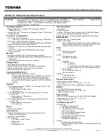
2. The CPU heat sink will be visible at point
(
Figure 7a
).
3. Loosen the CPU heat sink screws in the order
,
,
, ,
&
(the reverse order as indicated on the
label
Figure 7a
).
4. Grip the heat sink tab and carefully lift the heat sink up and off the computer (
Figure 7b
).
A
6
5
4
3
2
1
7
Figure 7
Processor Removal
a. The CPU heat sink will
be visible at point
.
Remove the screws from
the CPU heatsink.
b. Grip the heat sink tab
and carefully lift the heat
sink up and off the com-
puter.
A
7. Heat Sink
• 6 Screws
a.
b.
1
2
3
A
7
6
5
4
Summary of Contents for W251ESQ
Page 1: ...W251ESQ W255ES ...
Page 2: ......
Page 3: ...Preface I Preface Notebook Computer W251ESQ W255ES Service Manual ...
Page 43: ...Top W251ESQ A 3 A Part Lists Top W251ESQ 灰色 尚盟 非耐落 Figure A 1 Top W251ESQ ...
Page 44: ...A 4 Top W255ES A Part Lists Top W255ES 灰色 尚盟 非耐落 Figure A 2 Top W255ES ...
Page 45: ...Bottom A 5 A Part Lists Bottom Figure A 3 Bottom ...
Page 46: ...A 6 SATA BLU RAY COMBO A Part Lists SATA BLU RAY COMBO 非耐落 志精 Figure A 4 SATA BLU RAY COMBO ...
Page 47: ...DVD DUAL A 7 A Part Lists DVD DUAL Figure A 5 DVD DUAL 非耐落 志精 ...
Page 48: ...A 8 LCD A Part Lists LCD 頭厚 非耐落 中性 Figure A 6 LCD ...
Page 49: ...LCD A 9 A Part Lists ...
Page 50: ...A 10 A Part Lists ...
Page 102: ...Schematic Diagrams B 52 B Schematic Diagrams ...