background image


POWER GUN SUCTION BLAST TOOLS 

Page 2 


© 2018 CLEMCO INDUSTRIES CORP.  

  www.clemcoindustries.com  

  Manual No. 24189, Rev. C 06/18 


Figure 1 


1.4 General 

Description 


1.4.1

  This manual covers two Power Gun models. 

Both models are available with or without the cart and 3 
cuft hopper. 
 
Conventional Power Gun: limited to dry blasting only. 
 
Power Gun Model H2O: can be used for dry blasting and 
has water connections to add water into the blast 
stream. 
 

1.4.2

  Power Guns are ideally suited for light-duty, 

small, and touchup blasting jobs. The performance of the 
Power Gun approaches that of a small pressure system, 
but does not require a pressure vessel nor does it require 
the setup time and maintenance of a pressure system. 


1.5 

Components and Operating Principles


1.5.1 Components


1.5.1.1 

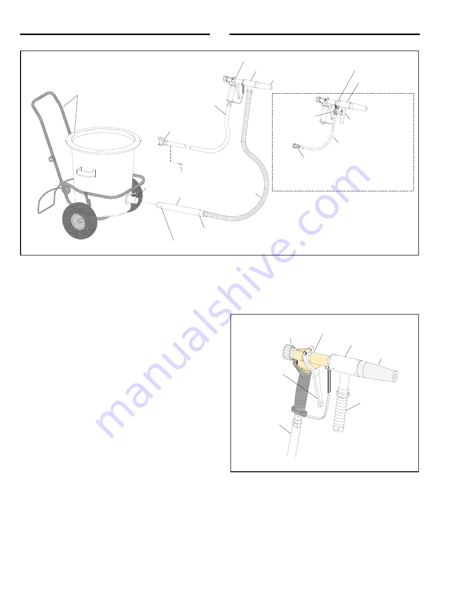
Components of the Power Guns are shown in 

Figure 1, the gun assembly is shown in Figure 2, and the 
additional parts for the Model H2O wetblast gun 
assembly are shown in Figure 3. 
 

1.5.2 Operating 

Principles 


1.5.2.1

  When compressed air is supplied to the gun and 

the trigger is pulled, air flows through the gun, creating a 
partial vacuum in the material hose. As a result, abrasive  
 

is drawn into the lance, through the material hose, and 
into the mixing chamber. Abrasive mixes with the air 
stream within the mixing chamber and is propelled 
through the nozzle onto the surface being blasted. 


 Figure 


1.5.2.2

  Besides being an effective dry blaster, additional 

parts provided with the H2O model (shown in the insert 
in Figure 1 and Figure 3) include a water jacket and 
hose, which attaches to a municipal water supply 
(faucet). When the water supply is turned ON, the water 
valve allows the operator to turn water ON and OFF and 
regulate the amount of water added into the mixing 
chamber and blast stream. Water entering the blast 

Material Hose

Air Hose

Lance

Abrasive Inlet Holes

Air-Intake Holes 

Safety Lock Pin 

Connecting Collar 

Air-Hose 
Coupling 

Water Hose

Water Valve

Air-Induction Valve

Callouts within broken lines are additional 
items included with 

H2O

 model.

Mixing Chamber 

Some items rotated for clarity. 

Nozzle 

Mixing Chamber 
H2O Model

Water Jacket 

3/4" Water Connector

Gun Assembly 

Optional Cart with 
3 Cuft Hopper  

Blast-Pressure 

Control Knob

Air Hose

Material Hose 

Nozzle 

Mixing Chamber 

Gun Assembly 

Trigger

Dry Blast Gun Assembly 

Summary of Contents for 24189

Page 1: ...stries com www clemcoindustries com Do not use this equipment before READING this MANUAL and UNDERSTANDING its contents These WARNINGS are included for the health and safety of the operator and those in the immediate vicinity Failure to read and understand these warnings can result in injury or death Electronic files include a Preface containing the same important information as in the orange cove...

Page 2: ... WARNING Warning indicates a hazardous situation that if not avoided could result in death or serious injury DANGER Danger indicates a hazardous situation that if not avoided will result in death or serious injury 1 3 Table of Contents INTRODUCTION 1 0 Scope of Manual 1 1 Safety Alerts 1 2 Table of Contents 1 3 General Description 1 4 Components and Operating Principles 1 5 COMPRESSED AIR and ABRA...

Page 3: ...ed air flows through the gun creating a partial vacuum in the material hose As a result abrasive is drawn into the lance through the material hose and into the mixing chamber Abrasive mixes with the air stream within the mixing chamber and is propelled through the nozzle onto the surface being blasted Figure 2 1 5 2 2 Besides being an effective dry blaster additional parts provided with the H2O mo...

Page 4: ... Gun The table shows air consumption it does not show the recommended compressor size Check with a compressor supplier for compressor recommendations based on total compressed air requirements 2 1 2 For most applications the compressor should be large enough to maintain 80 100 psi under working conditions Delicate work may require lower pressure and tough applications may require higher pressure 2...

Page 5: ... 5 Open the faucet to supply water to the Power Gun 3 2 6 Begin dry blasting per Section 4 5 After dry blasting adjustments are made open the water valve as needed to regulate water flow Open the valve only enough to water to suppress dust and prevent it from being airborne 4 0 OPERATION NOTE Unless noted otherwise the sequence of operation in Sections 4 1 through 4 4 may be done in any order that...

Page 6: ...exposed to the hazards generated by abrasive blasting must wear appropriate protective gear including abrasive resistant clothing leather gloves eye and hearing protection and a NIOSH approved Type CE supplied air respirator 4 2 2 Don all protective blasting attire outside the blast area in a clean nonhazardous environment free of contaminants where the air is safe to breathe 4 2 3 When finished b...

Page 7: ...o have the water valve closed when the trigger is released can allow water to flow into the mixing chamber and material hose causing blockage from wet abrasive 4 6 4 To stop blasting close the water valve before releasing the trigger By not closing the water valve first will allow water to flow into the mixing chamber and material hose causing blockage 4 6 5 Wash Down While blasting loosen the air...

Page 8: ...knob clockwise decreases the blasting force for delicate jobs and turning it counterclockwise increases the blast force for tougher jobs Figure 9 5 2 Positioning of Hose and Gun Figure 10 5 2 1 Whether the operator is left or right handed could determine the most comfortable positioning of the handle grip and material hose To change the orientation of the material hose with that of the handle grip...

Page 9: ...m the sudden release of compressed air Lockout and tagout the compressed air supply Bleed the air supply line Periodically inspect the air jet mixing chamber nozzle and material hose for wear 6 1 Removing Nozzle and Air Jet There are no threads on the mixing chamber the jet and nozzle are held onto the mixing chamber with three setscrews Use a 2 5 mm hex key to loosen the setscrews and while twist...

Page 10: ... 2 5 mm hex key to loosen the three setscrews holding the jet to the mixing chamber and while twisting the jet to loosen it pull out to remove it from the chamber 6 4 2 Replace the air jet when wear reaches the orifice and affects the overall length New air jet orifices are 1 4 ID and extend approximately 1 5 16 from the jet body NOTICE When removing and installing an air jet do not put a wrench o...

Page 11: ...existing air jet from the gun assembly NOTE Breakaway thread sealant is used on the threads between the air jet and gun The sealant prevents parts from rotating out of alignment during operation The recommended method for removing the air jet is with a strap wrench or similar tool that will not damage the outside surface of the jet If a suitable wrench is not available use a pipe wrench or slip jo...

Page 12: ...led using thread sealant 7 3 3 Note which side the water valve handle is facing After the jacket is removed the valve may be rotated to the left or right side whichever is most comfortable for the operator 7 3 4 Remove the water jacket jet assembly from the gun and if necessary rotate the water valve so the handle is in the most comfortable side for the operator to adjust 7 3 5 Apply breakaway thr...

Page 13: ...se If the material hose packs with abrasive it is a sign that the abrasive mixture is too rich Make sure the air intake holes in the lance are open When using the lance into bagged abrasive make sure the intake holes are not buried in abrasive 8 1 3 Worn nozzle Replace the nozzle when the orifice is worn to 9 16 or sooner if production decreases noticeably 8 1 4 Air jet worn Inspect end of air jet...

Page 14: ...2 to 1 1 4 OD hose 15012 Conversion kit dry blast to wetblast items in Fig 20 with 16 ft water hose 29255 with 30 ft water hose 29339 Figure 20 9 2 Power Gun Systems Description Stock No Power Gun with 3 cuft cart and hopper with 16 ft air and material hose 99860 with 30 ft air and material hose 24687 Power Gun without cart and hopper with 16 ft air and material hose 90253 with 30 ft air and mater...

Page 15: ...eet required 16 ft and 30 ft are standard lengths 24778 4 Hose air bulk specify feet required 16 ft and 30 ft are standard lengths 24779 5 Clamp material hose 24780 6 Clamp 3 4 OD band 28018 7 Coupling air hose 00595 8 Lock pin package of 25 11203 9 Hopper and lid 3 cuft 25589 10 Cart assembly 25591 11 Hopper and cart assembly 3 cuft 99899 12 Hose assembly coupled air includes three of Item 6 one ...

Page 16: ...ipple 1 8 x 1 4 reducing 29252 9 Valve 1 4 NPT ball shutoff 29254 10 Clamp 1 2 ID hose 29658 11 Hose 1 4 ID water bulk per foot specify length required 04911 12 Hose fitting 1 4 MNPT x 1 4 barb 02714 13 Bushing 1 2 x 1 4 brass 02706 14 Adaptor 1 2 FPT x 3 4 fem water swivel 02705 15 Washer pack of 6 04370 16 Sleeve air induction valve 100492 17 Knob tensioning 100493 18 Screw M4 x 5 socket head 10...

Page 17: ...vice kit gun assembly includes items 1 thru 12 90208 1 Knob control 90584 2 Bushing knob stem 90585 3 Nut control knob retaining 90586 4 Stem control knob 90587 5 Screw stem stop 90588 6 Spring control knob 90589 7 Spring return 90590 8 Guide rod 90591 9 Setscrew rod guide 90592 10 Plug rod and seal 90593 11 Rod and tip assembly 90594 12 Seal rod 90595 13 Gun body and trigger assembly Not availabl...

Reviews: