


Page 4
823036EN
02/11/2014
Cleco
®
Product Information
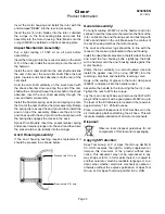
Remove the hammer from the vise and slip the cam
shaft and related components from the rear of the cam.
Remove the shock absorber (slight press fit) from the
rear of the cam shaft. The will allow removal of the
insulator, butt plate, cam roller and cam roller shaft.
Slip the cam from the rear of the hammer using caution
not to lose the timing pin.
Motor Unit Disassembly:
Place the front of the motor housing on a cylinder (4-1/2”
I.D. x 5” long) and using a driver with a 2-1/8” O.D. drive
the rotor out of the rear bearing. This will allow removal
of the front bearing plate, rotor blades and rotor from the
housing.
Invert the housing on the fixture and use the rotor to
drive the rear bearing plate assembly from the housing.
The cylinder should not be removed from the housing
unless replacement is necessary. If cylinder replacement
is necessary, a 4-5/32” O.D. bushing driver (with a
suitable relief for the alignment key) should be used to
press the cylinder out of the housing.
Remove the rotor bearings from the bearing plates. It
is recommended that the rotor shaft seals be replaced
every time the tool is serviced.
Note: Unless the o-rings located on the O.D. of the
bearing plates are severely damaged, they should
not be removed. If o-ring replacement is required, the
new o-rings must be installed using a fast cure contact
adhesive such as Loctite 404.
For cleaning and inspection of the muffler plates, remove
the retainer screw.
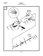
Handle Disassembly:
Disassembly of the inside trigger and outside trigger
models are the same procedure.
Removing the air inlet bushing will allow removal of
the o-ring, air inlet screen, throttle valve spring, throttle
valve, throttle valve seal and throttle valve pin.
Do not remove the throttle pin bushing unless
replacement is necessary. To remove the throttle pin
bushing, tap the I.D. of the bushing using a 1/4”-20
thread tap and then insert a 1/4”-20 bolt of adequate
length and clamp the bolt in a vise. Carefully drive the
handle away from the vise using a soft mallet.
If the trigger requires replacement, only the trigger pin
needs to be removed.
Maintenance - Reassembly:
Cleaning and Inspection:
Clean all parts in a solvent and inspect for excessive
wear or damage. If the rotor blades measure less than
7/16” wide on either end they must be replaced. Rotor
bearings should be replaced if they feel rough after
cleaning or show excessive looseness.
Handle Assembly:
When installing the trigger use a pin slightly smaller than
the hole in the handle to locate the trigger when driving
the trigger pin into the handle.
If the throttle valve bushing was removed, the replacement
bushing must be pressed in to a depth of 1-15/16” plus
or minus 1/64” from the bottom face of the handle.
Inspect the throttle valve seal for wear or damage. If
replacement is necessary, push the new seal (cupped
face first) onto the throttle valve from the tapered end.
Clean the threads on the air inlet bushing and replace the
o-ring if necessary. Apply Loctite® # 271 to the threads.
Install the throttle valve pin and throttle valve assembly
into the handle. Place the air inlet screen and throttle
valve spring into the air inlet bushing and assemble into
the handle. Tighten the air inlet bushing to a minimum of
80 ft. lbs. torque.
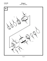
Motor Unit Assembly:
Install the muffler plates into the motor housing and
secure with the retaining screw.
During reassembly of the bearing plates, the rotor
shaft seals should be installed with their “lips” facing
out (visible after installation). When installing the rotor
bearings press on the bearing’s outer race. Lubricate
both the seals and rotor bearings with 30W oil before
assembly into the motor unit.
Inspect the o-ring on the front bearing plate and replace
if necessary.
Note: The bearing plates are identical.
However, this o-ring is only used on the front bearing
plate.
If the cylinder was removed, the new cylinder (with
alignment key in position) must be pressed in from the
rear of the motor housing to a depth of 5/8” from the rear
face of the motor housing.
Lubricate the o-rings on the O.D. of the rear bearing
plate and press this assembly into the motor housing.
During installation, make sure the o-rings line up with
the air ports in the motor housing.