


Page 3
823036EN
02/11/2014
Cleco
®
Product Information
The original language of this manual is English.
Product Safety Information:
Intended Use:
This air assembly tool is intended for tightening of
threaded joints or running down fasteners. Use only for
their designated purpose. Do not use as a hammer, lever
or other improper usage that can cause tool damage
and operator injury.
For additional product safety information refer to Apex
Tool Group, LLC or Apex Tool Group GmbH & Co. OHG
document CE-2004, General Safety Impact Wrenches.
This air assembly tool must not be modified unless
approved in writing by Apex Tool Group, LLC or Apex
Tool Group GmbH & Co. OHG. All safety devices must
be properly installed and maintained in good working
order.
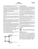
Air Line Lubrication:
Use Apex Tool Group, LLC or Apex Tool Group GmbH
& Co. OHG’s lightweight air tool oil 500021 (available
in quantities shown in the following chart) or an SAE-5
lightweight spindle oil.
Oil Reservoir (30W):
The oil reservoir marked “30W Oil” should not require
attention until the tool is disassembled for regular
inspection and maintenance. However, it is suggested
that the oil level be checked periodically. If oil is required,
approximately 1.25 fluid ounces of a good grade 30W oil
should be added to the reservoir.
Air Supply Line:
Service and Repair:
Tool service and repair should be performed by a
properly trained technician or an authorized Apex
Tool Group, LLC or Apex Tool Group GmbH & Co.
OHG Center. Refer to the last page of this manual for
locations.
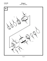
General Disassembly:
Always disconnect the air supply before performing any
maintenance on these tools.
Remove the four (4) hex nuts and washers from the
handle area. Remove the handle assembly, reversing
valve, handle gasket and the motor clamp seal from the
motor housing.
Drive the four housing bolts out the front of the motor
assembly. The anvil housing assembly can now be
removed allowing the impacting mechanism to slip out
the front of the motor assembly. It may be necessary to
rotate the anvil housing to clear the anvil and hammer
lugs.
Anvil Housing Disassembly:
It is recommended that the anvil housing seal (867993)
be replaced every time the tool is serviced. The seal can
be pried out using a screwdriver.
The anvil housing seal must be removed if the anvil
housing bushing requires replacement. The anvil
housing bushing can be pressed out the rear of the anvil
housing using a 2-3/16” diameter bushing driver.
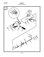
Impact Mechanism Disassembly:
Clamp the hammer, horizontally, in a soft jawed vise
and drive the anvil away from the hammer using a soft
mallet. This will permit the anvil pin, spring clip and
hammer spring to be removed from the front of the cam
shaft.
Note: Spline drive models, if any of the socket retainer
parts require replacement, a 5/32” hole should be drilled
in the socket retainer plunger. Refer to the following
illustration. Insert a pin punch into the drilled hole and
lightly tap the punch under the socket retainer pin. Pry
on the punch to pop the pin out of the pocket in the
plunger.
WARNING
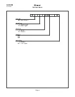
Part No.
Packaged
Designation
540397
1 Quart (0.94 liter)
Airlube 10W/NR-420LB DR
533485 1 US Gallon (3.78 liter) Airlube 10W/NR-420LB DR
Parameter
Description
Air Hose
Hose diameter: 1/2" (12,7 mm)
Maximum length: 16.4' (5 m)
Working pressure
range
58 to 101.5 psi (400 to 700 kPa)
Recommended: 90 psi (620 kPa)
Compressed air
Air quality according to ISO 8573-1,
quality class 2.4.3
The compressed air must be clean and dry.
5/32” Drilled Hole