7
OPERATING INSTRUCTIONS
READ SAFETY RECOMMENDATION BEFORE
CONNECTING TOOL.
The 15GEL Series Grinders are designed to operate on 90
psig (6.2 bar) maximum air pressure, using a 3/8" hose up
to 8' in length. If additional length is required, the next larger
hose size may be connected to the 8' whip hose.
LUBRICATION
An automatic in-line filter- regulator- lubricator is recom-
mended as it increases tool life and keeps the tool in
sustained operation. The in-line lubricator should be regu-
larly checked and filled with a good grade of 10W machine
oil. Proper adjustment of the in-line lubricator is performed
by placing a sheet of paper next to the exhaust ports and
holding the throttle open approximately 30 seconds. The
lubricator is properly set when a light stain of oil collects on
the paper. Excessive amounts of oil should be avoided.
STORAGE
In the event that it becomes necessary to store the tool for
an extended period of time (overnight, weekend, etc.), it
should receive a generous amount of lubrication at that
time and again when returned to service. The tool should be
stored in a clean and dry environment.
SERVICE INSTRUCTIONS
DISASSEMBLY - GENERAL
Remove the tool from the air supply and clamp the flats of
the backhead in a soft-jawed vise and unscrew (left hand
threads) the spindle housing. Remove the motor unit from
the backhead.
DISASSEMBLY - SPINDLE HOUSING
Use a 9/16" six (6) point socket to unscrew splined nut, No.
202236, from the spindle. Remove the spindle from the
front of the spindle housing. Bearing retainer nut, No.
202258, has left hand threads.
DISASSEMBLY - MOTOR UNIT
Use a 3/16" hex wrench to hold the rotor and unscrew (left
hand threads) the governor assembly. Note: Remove the
governor spring at this time to prevent its loss. Use a 9/16"
six (6) point box wrench to unscrew the splined nut, No.
202236. Use a suitable driver to drive the front rotor shaft
out of the front rotor bearing. After removing the cylinder
and rotor blades, the rear rotor shaft may be driven out of
the rear bearing.
DISASSEMBLY- BACKHEADS
Remove the oiler body from the front of the backhead. The
throttle valve on lever throttle backheads may be removed
by unscrewing the valve cap, No. 864531.
Inlet screens should be washed in a solvent and blown out
in the reverse of normal air flow. Replace screens if clogged
or torn.
REASSEMBLY- GENERAL
The tool is reassembled in the reverse order of disassem-
bly. Clean parts in a solvent and inspect for damage or
wear. Replace any bearing that feels rough or has exces-
sive play.
REASSEMBLY- MOTOR
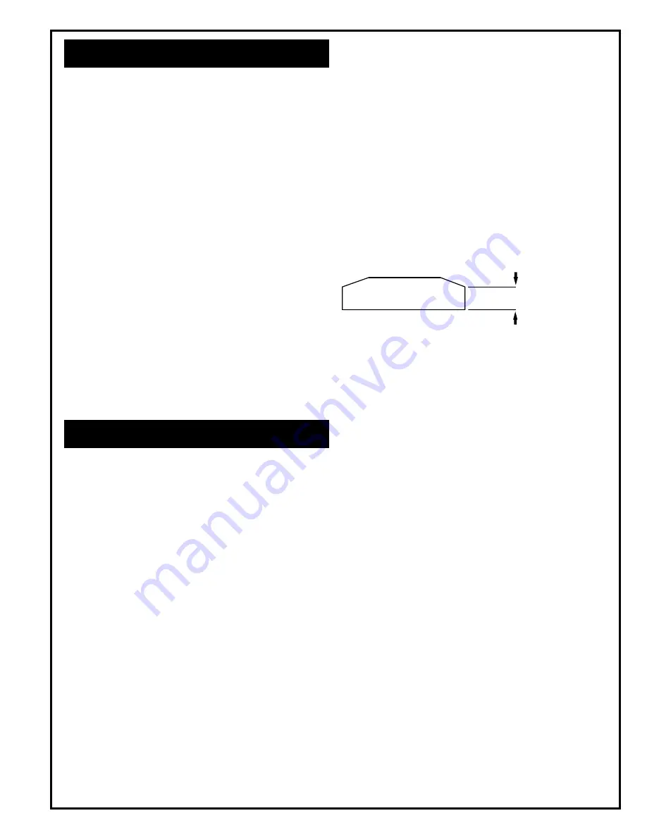
It is recommended that new rotor blades be installed at
each repair cycle. If not replaced, the used ones must
measure a minimum of 7/32" (5.6mm) at both ends. Failure
of these parts could cause damage to more expensive
components Also, be sure that the blades are no longer
than the rotor.
Assemble the front rotor bearing and front bearing plate and
support the bearing on its outer race. Measure from the face
of the bearing plate to the bearings inner race. Select or fit
by sanding, a rotor collar .0015"(.0038mm) to .0025"
(.076mm) longer than this measurement.
When installing the splined nut, No. 202236, on the rotor,
the undercut end should be toward the bearing. Assemble
the rotor blades (4), cylinder, rear bearing plate, rotor
bearing, RPM adjustment screw (hex toward front of rotor),
governor spring, and governor assembly on the rotor.
Check the governor for smooth operation. Tighten the
splined nut and governor securely.
REASSEMBLY- SPINDLE HOUSING
When installing the two (2) front spindle bearings, No.
202234, the shielded side should be assembled to the rear
of the tool. Bearing spacer, No. 864635, must be in place
between the two (2) bearings. Splined nut, No. 202236,
should be assembled with the undercut end to the rear of
the housing.
FINAL ASSEMBLY - COMPLETE TOOL
Tighten all joints securely and check the free speed (RPM)
of the tool with a dependable tachometer. To adjust the
RPM setting, shut off the air supply and remove (left hand
threads) the extension housing assembly and use gover-
nor adjusting wrench, No. 867027, to adjust the RPM adju-
stment screw. Rotate the screw clockwise (CW) to increase
the RPM setting and counter-clockwise (CCW) to decrease
the RPM setting.
CAUTION: After the grinder is reassembled, be sure to
check the free speed (RPM) for proper speed with a
dependable tachometer before returning the grinder to
service.
Must be replaced if
7/32" (5.6mm) or less
at either end.
Summary of Contents for 15GEL Series
Page 11: ...11 NOTES...


