


Maintenance
5-4
750-204
Profire D/LND
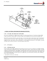
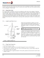
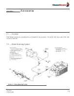
5.5 — Pilot and Ignition Electrode
The ignition transformer requires little attention other than making sure the ignition wire is firmly attached to the
transformer and the electrode.
FIGURE 5-4.
Ignition Pilot Electrode Setting
Be sure the wire insulation is in good condition and not grounded. Failure to keep the ignition electrode clean
and properly set can cause faulty operation. The pilot assembly is supported by a socket in the diffuser and gas
inlet tube. No adjustment is required except proper positioning of the electrode wire.
5.6 — Flame Scanner
The scanner must be clean. Even a small amount of contamination will reduce the flame signal. Wipe the scan-
ner lens with a clean soft cloth.
5.7 — Oil Nozzle
Successful burner operation requires use of the proper style nozzle tip and keeping the orifice clean. Standard
nozzle tips furnished on the burners are of a special emulsifying type which delivers a spray of extreme fineness
and at an angle which insures proper mixing with the air stream. Unsatisfactory performance and loss of effi-
ciency can result from the use of non-standard nozzle tips. If the burner flame becomes stringy or lazy, it is pos-
sible that the nozzle spring is not properly in place or the nozzle is clogged. This problem is usually indicated by
an abnormally high reading on the atomizing air pressure gauge on the air-oil tank.
To remove the nozzle:
1.
Disconnect the oil and air tubes from the nozzle assembly.
2.
Loosen the three 1/4” screws holding the nozzle spider bracket to the support ring.
3.
Withdraw the nozzle and bracket assembly.
4.
Clean the nozzle tip by unscrewing the tip from the nozzle body. Use care not to distort the tube.
Summary of Contents for ProFire D Series
Page 2: ......
Page 8: ......
Page 16: ...viii 750 204 Profire D LND...
Page 30: ...Installation 2 2 750 204 Profire D LND FIGURE 2 1 Recommended Scotch Marine Chamber Dimensions...
Page 39: ...750 204 Profire D LND 2 11 2 13 Installation Checklist FIGURE 2 7 Recommended Pipe Size...
Page 40: ...Installation 2 12 750 204 Profire D LND FIGURE 2 8 Recommended Pipe Size...
Page 42: ...Installation 2 14 750 204 Profire D LND FIGURE 2 10 Recommended Pipe Size...
Page 43: ...750 204 Profire D LND 2 15 2 13 Installation Checklist FIGURE 2 11 Recommended Pipe Size...
Page 44: ...Installation 2 16 750 204 Profire D LND FIGURE 2 12 Recommended Pipe Size...
Page 45: ...750 204 Profire D LND 2 17 2 13 Installation Checklist FIGURE 2 13 Recommended Pipe Size...
Page 46: ...Installation 2 18 750 204 Profire D LND FIGURE 2 14 Recommended Pipe Size...
Page 50: ...Installation 2 22 750 204 Profire D LND...
Page 69: ...750 204 Profire D LND 4 11 4 8 Firing Rate Controls FIGURE 4 7 Motor Rotations...
Page 70: ...Adjustments 4 12 750 204 Profire D LND...
Page 82: ...Maintenance 5 12 750 204 Profire D LND...
Page 88: ...Troubleshooting 6 6 750 204 Profire D LND...
Page 98: ...Flue Gas Recirculation 8 6 750 204 Profire D LND FIGURE 8 4 FGR Piping and Valve Sizes...
Page 100: ...Flue Gas Recirculation 8 8 750 204 Profire D LND FIGURE 8 6 20 PPM Head Assembly...
Page 106: ...Parts Lists and Drawings 9 6 750 204 Profire D LND 9 4 2 Blast Tube Assembly D378 420...
Page 108: ...Parts Lists and Drawings 9 8 750 204 Profire D LND 9 4 3 Blower Housing Assembly D42 175...
Page 110: ...Parts Lists and Drawings 9 10 750 204 Profire D LND 9 4 4 Blower Housing Assembly D210 336...
Page 112: ...Parts Lists and Drawings 9 12 750 204 Profire D LND 9 4 5 Blower Housing Assembly D378 420...
Page 114: ...Parts Lists and Drawings 9 14 750 204 Profire D LND 9 4 6 Compressor Set D42 145...
Page 116: ...Parts Lists and Drawings 9 16 750 204 Profire D LND 9 4 7 Compressor Set D175 336...
Page 118: ...Parts Lists and Drawings 9 18 750 204 Profire D LND 9 4 8 Compressor Set D378 420...
Page 120: ...Parts Lists and Drawings 9 20 750 204 Profire D LND 9 4 9 Control Package Fireye...
Page 122: ...Parts Lists and Drawings 9 22 750 204 Profire D LND 9 4 10 Control Package Honeywell...
Page 124: ...Parts Lists and Drawings 9 24 750 204 Profire D LND 9 4 11 Damper Assembly D42 420...
Page 126: ...Parts Lists and Drawings 9 26 750 204 Profire D LND 9 4 12 Damper Assembly LND42 420...
Page 128: ...Parts Lists and Drawings 9 28 750 204 Profire D LND 9 4 13 Drawer Assembly D42 63...
Page 130: ...Parts Lists and Drawings 9 30 750 204 Profire D LND 9 4 14 Drawer Assembly D84 145...
Page 132: ...Parts Lists and Drawings 9 32 750 204 Profire D LND 9 4 15 Drawer Assembly D175 336...
Page 134: ...Parts Lists and Drawings 9 34 750 204 Profire D LND 9 4 16 Drawer Assembly D378 420...
Page 136: ...Parts Lists and Drawings 9 36 750 204 Profire D LND 9 4 17 Firing Head Assembly D42 420...
Page 139: ...750 204 Profire D LND 9 39 9 4 Parts Lists and Drawings 9 4 19 Oil Heater D42 420...
Page 146: ...Parts Lists and Drawings 9 46 750 204 Profire D LND 9 4 22 Oil Metering Assembly D378 420...
Page 156: ...750 204 Profire D LND...
Page 159: ......
Page 160: ......