


Installation
2-8
750-204
Profire D/LND
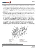
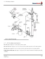
An oil circulating pump provides continuous oil circulation to the circulation loop. A back pressure valve holds
10 to 15 PSI on the loop system. With the oil supply line connected only to the oil metering pump inlet, all oil
must pass through the pump. During pre-purge, unmetered oil flows through a bypass section of the oil metering
pump. Metered oil passes through the metering section to a de-energized 3-way oil valve (common port). Both
unmetered and metered oil must pass through the back pressure valve and return to an oil storage tank. The oil
metering pump will only meter oil. It will not serve as a circulating pump. At trial for main flame (main fuel), the
3-way oil valve is energized admitting metered oil to the nozzle for atomization and fast smooth ignition. Unmet-
ered oil continues to flow through the bypass section of the oil metering pump and returns to an oil storage tank.
2.8 — Circulating Oil Pump
A circulating oil pump is required to deliver fuel oil from the storage tank to the burner at a minimum of 150% of
the maximum burner firing rate. The excess oil allows a margin for piping error, viscosity changes in the fuel oil,
and circulating pump wear. Correct pipe sizing is determined by circulating rate, not burner capacity. Install the
pump as close to the supply tanks as possible. Suction lift should be as low as possible. Maximum suction of
15” Hg vacuum is good practice for either light or heated heavy oil. The strainer should be installed in the suc-
tion line just ahead of the circulating pump to prevent foreign material from entering the pump. Locate the
strainer so it may be easily cleaned.
2.9 — Oil Loop Heater
This heater should heat the fuel oil for proper burning at full firing rate. The proper oil temperature is that which
gives the best results with the particular oil being fired. This may vary widely with different fuels in different firing
systems. Residual oil viscosity can vary widely within grade limits and is not always within the specified limits of
the grade. Fuel viscosity requirements for air atomizing burners are not critical. Under typical circumstances, a
viscosity of 100 SSU might be optimum, but good results may be obtained up to 150 SSU. There is no advan-
tage to less than 100 SSU.
Where the burning characteristics of the fuel are unknown, the following may be considered as typical:
2.10 — Burner Mounted Trim Heater
An auxiliary trim heater is in line between the metering pump and 3-way oil valve. The auxiliary trim heater is
used for topping off oil temperature prior delivery to the nozzle.
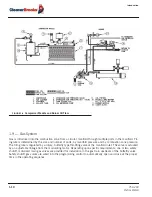
2.11 — Back Pressure Valve
A back pressure valve, similar to Watson McDaniel type “R,” needs to be installed on the return line as shown in
Figure 2-6. This valve must be installed in an upright vertical position. Before installing the valve, be sure to
No. 4
80º - 125º F
No. 5L
115º - 160º F
No. 5H
145º - 180º F
No. 6
180º - 220º F
Summary of Contents for ProFire D Series
Page 2: ......
Page 8: ......
Page 16: ...viii 750 204 Profire D LND...
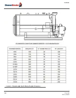
Page 30: ...Installation 2 2 750 204 Profire D LND FIGURE 2 1 Recommended Scotch Marine Chamber Dimensions...
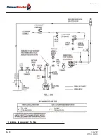
Page 39: ...750 204 Profire D LND 2 11 2 13 Installation Checklist FIGURE 2 7 Recommended Pipe Size...
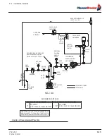
Page 40: ...Installation 2 12 750 204 Profire D LND FIGURE 2 8 Recommended Pipe Size...
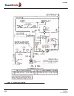
Page 42: ...Installation 2 14 750 204 Profire D LND FIGURE 2 10 Recommended Pipe Size...
Page 43: ...750 204 Profire D LND 2 15 2 13 Installation Checklist FIGURE 2 11 Recommended Pipe Size...
Page 44: ...Installation 2 16 750 204 Profire D LND FIGURE 2 12 Recommended Pipe Size...
Page 45: ...750 204 Profire D LND 2 17 2 13 Installation Checklist FIGURE 2 13 Recommended Pipe Size...
Page 46: ...Installation 2 18 750 204 Profire D LND FIGURE 2 14 Recommended Pipe Size...
Page 50: ...Installation 2 22 750 204 Profire D LND...
Page 69: ...750 204 Profire D LND 4 11 4 8 Firing Rate Controls FIGURE 4 7 Motor Rotations...
Page 70: ...Adjustments 4 12 750 204 Profire D LND...
Page 82: ...Maintenance 5 12 750 204 Profire D LND...
Page 88: ...Troubleshooting 6 6 750 204 Profire D LND...
Page 98: ...Flue Gas Recirculation 8 6 750 204 Profire D LND FIGURE 8 4 FGR Piping and Valve Sizes...
Page 100: ...Flue Gas Recirculation 8 8 750 204 Profire D LND FIGURE 8 6 20 PPM Head Assembly...
Page 106: ...Parts Lists and Drawings 9 6 750 204 Profire D LND 9 4 2 Blast Tube Assembly D378 420...
Page 108: ...Parts Lists and Drawings 9 8 750 204 Profire D LND 9 4 3 Blower Housing Assembly D42 175...
Page 110: ...Parts Lists and Drawings 9 10 750 204 Profire D LND 9 4 4 Blower Housing Assembly D210 336...
Page 112: ...Parts Lists and Drawings 9 12 750 204 Profire D LND 9 4 5 Blower Housing Assembly D378 420...
Page 114: ...Parts Lists and Drawings 9 14 750 204 Profire D LND 9 4 6 Compressor Set D42 145...
Page 116: ...Parts Lists and Drawings 9 16 750 204 Profire D LND 9 4 7 Compressor Set D175 336...
Page 118: ...Parts Lists and Drawings 9 18 750 204 Profire D LND 9 4 8 Compressor Set D378 420...
Page 120: ...Parts Lists and Drawings 9 20 750 204 Profire D LND 9 4 9 Control Package Fireye...
Page 122: ...Parts Lists and Drawings 9 22 750 204 Profire D LND 9 4 10 Control Package Honeywell...
Page 124: ...Parts Lists and Drawings 9 24 750 204 Profire D LND 9 4 11 Damper Assembly D42 420...
Page 126: ...Parts Lists and Drawings 9 26 750 204 Profire D LND 9 4 12 Damper Assembly LND42 420...
Page 128: ...Parts Lists and Drawings 9 28 750 204 Profire D LND 9 4 13 Drawer Assembly D42 63...
Page 130: ...Parts Lists and Drawings 9 30 750 204 Profire D LND 9 4 14 Drawer Assembly D84 145...
Page 132: ...Parts Lists and Drawings 9 32 750 204 Profire D LND 9 4 15 Drawer Assembly D175 336...
Page 134: ...Parts Lists and Drawings 9 34 750 204 Profire D LND 9 4 16 Drawer Assembly D378 420...
Page 136: ...Parts Lists and Drawings 9 36 750 204 Profire D LND 9 4 17 Firing Head Assembly D42 420...
Page 139: ...750 204 Profire D LND 9 39 9 4 Parts Lists and Drawings 9 4 19 Oil Heater D42 420...
Page 146: ...Parts Lists and Drawings 9 46 750 204 Profire D LND 9 4 22 Oil Metering Assembly D378 420...
Page 156: ...750 204 Profire D LND...
Page 159: ......
Page 160: ......