ClearView Corp. Ltd. Page 11 / 29
KR423I Encoder Modualtor User Manual
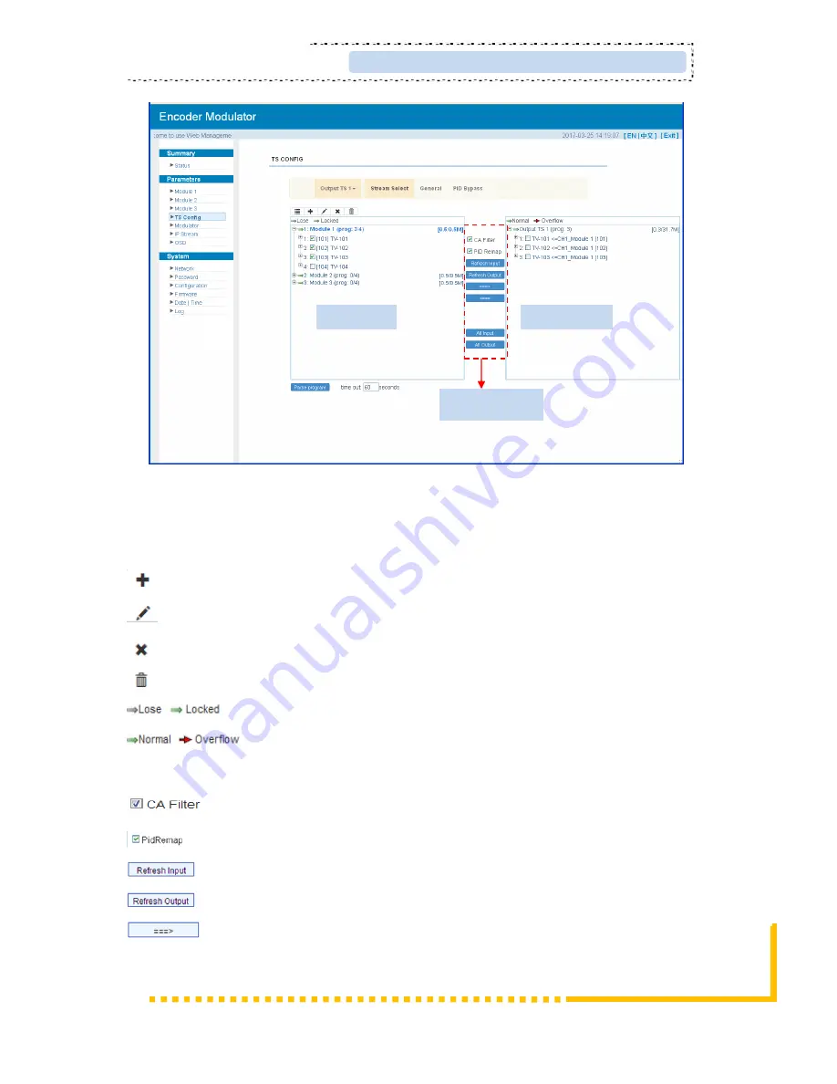
Figure-4
Configure ‘Input Area’ and ‘Output Area’ with buttons in ‘Operation Area’. Instructions are
as below:
: To add input channel which can from GE1/GE2/Connector
: To edit the input channel
: To delete the input channel
: To delete all inputs channel
: To check input IP lock or not, green means current IP locked
: To check current TS overflow or not, red color means current TS
overflow, need reduce program
: To filter/not filter the source CA information
: To enable/disable the PID remapping
To refresh the input program information
To refresh the output program information
Select one input program first and click this button to transfer the selected
program to the right box to output.
Input Area
Output Area
Operation Area


