COLLABORATE Versa Lite CT
9
QSG-0091-001 v1.0 June 2020
Quick-Start Guide
6. Route the cables through the hole.
Note the following:
• Carefully run connected cables so they do not block the cooling vents or put strain on the connectors.
• Anchors and screws used to mount the expander are not provided and must be selected by installer for the type of
ceiling material supporting the expander. Take care while drilling and installing anchors so ceiling material does not
tear out and weaken attachment.
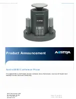
Figure 1. BMA-CTH Back Panel
Step 3: Connect the Components
a. Description of Controls and Connections
Description
a
Speakers Out. Two Phoenix Euroblock connectors for external 8 ohm speakers
b
PoE In: RJ45 connector. The Versa Lite CT does not use this connector. The Versa USB provides power to the
BMA CTH through the P-Link In connector.
c
Power Select sliding switch. Position determines power source – either left for PoE In or right for P-Link In. With a
Versa Lite CT, this switch is set to the right for P-Link In.
d
P-Link In: RJ45 connector. Receives power, audio, and control from the Versa USB.
e
P-Link Out: RJ45 connector. Connects to another P-Link device that requires power, such as a Bluetooth Expand-
er.
BMA CTH
Warning:
Power over Ethernet (PoE) equipment used with COLLABORATE® Versa Lite CT must meet the IEEE 802.3af or 802.3at
standards.
You should use the PoE Power Injector provided with Versa Lite CT. Other power source equipment may immediately ap-
ply power and could damage the Versa Lite CT components.
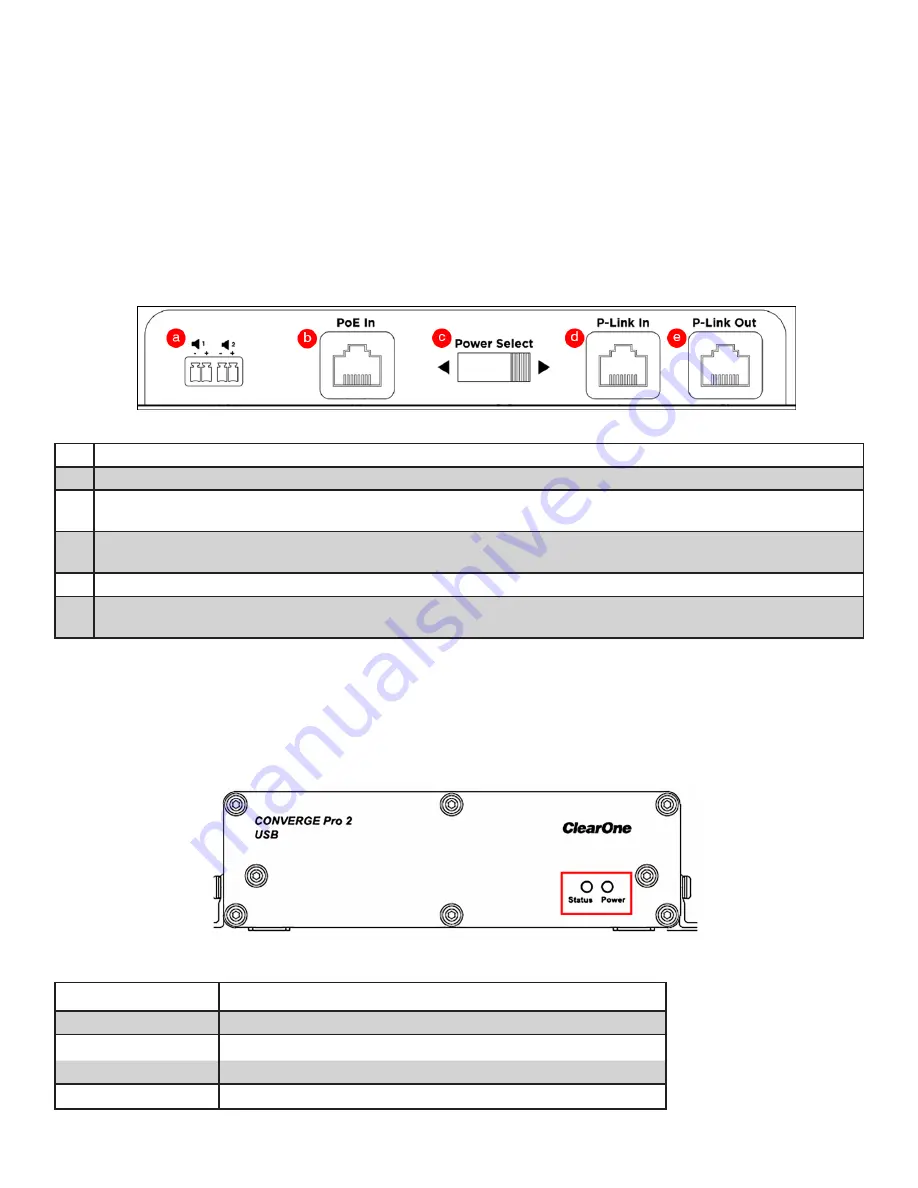
Versa USB
Figure 2. COLLABORATE Versa USB Front Panel
Status Indicator
LED Color
Meaning
Not lighted
No P-Link plugged in (attached?)
Solid Blue
P-Link plugged in; system working normally
Flashing Blue
Locate mode initiated from CONSOLE AI Lite
Solid Red
Error condition