Clear-Com WBS-670 Operating Instructions Manual Download Page 54

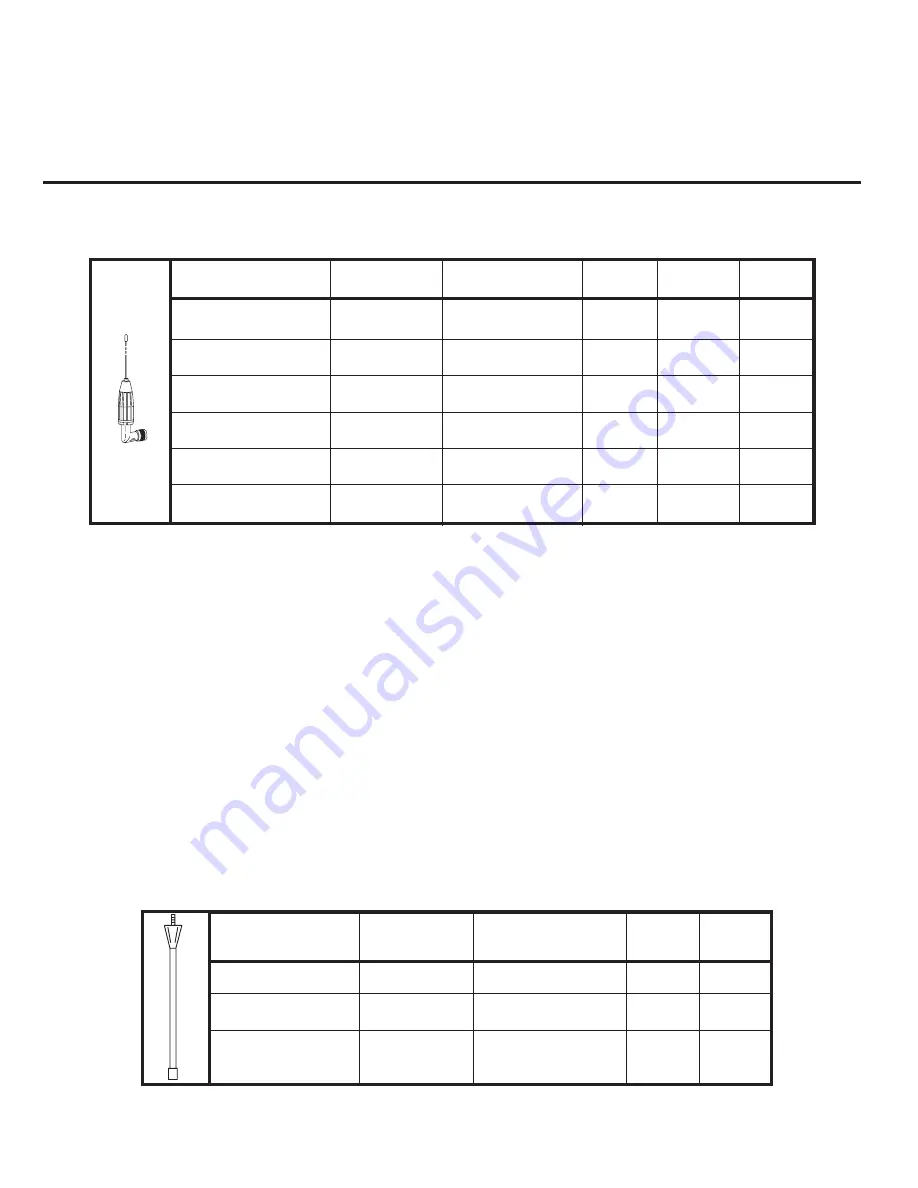
Base Station’s AN-680 1/2 - Wave Antennas

Beltpack’s AN-685 1/4-Wave Antenna

Accessories and Replacement Parts

12-1

S

ection

12

Part No.

Band Color

Frequency

C6

A2

B4

AN-680/C

Red

615-659.9 MHz

Rx

AN-680/E

Green

690-724.9 MHz

Rx

AN-680/G

Pink

515-548 MHz

Tx

AN-680/H

Brown

542-575 MHz

Tx

AN-680/A

Blue

520-564.9 MHz

Tx

AN-680/D

White

660-689.9 MHz

Rx

WTR Battery pack, alkaline

(batteries not included) .........................................

WTR-BC

WTR Nickel Metal Hydride

Battery pack .......................................................

WTR-BAT

Slot "Smart" Charger

with Four Nickel Metal

Hydride Battery Packs

U.S./Canada ........................................................

WTR-CHGR

Euro...............................................................

WTR-CHGR/220

Part No.

Band Color

Frequency

C6

A2

AN-685/A

Black

485.0-553.9 MHz

Rx

AN-685/B

Yellow

554.0-635.9 MHz

Rx

AN-685/C

Green

636.0-725.9 MHz Tx

Tx

Summary of Contents for WBS-670

Page 1: ...Operating Instructions WBS 670 WTR 670 Professional Wireless Intercom System R Intercom Systems...

Page 2: ...of years of development work with many of the features developed from customer feedback We hope that your experience with this product is a pleasant one and hope to provide you with a continuing line...

Page 3: ...ction 4 5 Transmit Switches 4 5 Intercom Switch 4 6 Intercom Interface 4 6 Auxiliary Input Output 4 6 Beltpack Set Up 4 7 Battery Installation 4 7 Antenna Connection 4 8 Transmit Mode 4 8 Headset Conn...

Page 4: ...een 6 16 Scan 6 17 Talk Button Latch on Latch off 6 18 Special Key Sequences 6 18 Lockout 6 18 1st Use Default 6 18 Factory Default 6 18 System Walk Thru 7 1 Trouble Shooting 8 1 Tech Tips 9 1 Frequen...

Page 5: ...ht distances of 1 000 feet The high efficiency beltpacks provide 12 hours of uninter rupted operation using standard alkaline batteries System Features Frequency agile base station and beltpacks No ex...

Page 6: ...MALE XLR FEMALE MALE XLR SELECT LOGIC OUTPUT AUDIO AUXILIARY OUT IN OUT IN HEADSET 4 3 2 1 VOLUME LOGIC MIC GAIN AUXILIARY AUDIO INPUT TALK TALK INTERCOM INTERCOM INTERCOM C L E A R C O M R T S T E L...

Page 7: ...eadset connected to 12 9 Talk Overmod Light LED is green when talk button 11 is active A normal mic gain setting will cause the LED to flash red on the loudest speech levels If the gain is too high th...

Page 8: ...l The connectors are switched to the appropriate intercom configuration via the I C Select Switch 4 Wire An RJ 45 type jack compatible with Ma trix type intercom systems 6 Auxiliary Input Output One 3...

Page 9: ...ical Line Impedance 200 ClearCom Intercom Input Output Level Adjustable 1 Vrms typical Line Impedance 200 Auxiliary Input Adjustable 2 Vrms typical Auxiliary Output Adjustable 2 Vrms typical into 600...

Page 10: ...2 4 Blank...

Page 11: ...l speech levels If the gain is too high the LED will be red during the complete word at normal speech levels 3 Talk Light LED is on when the talk button is active 4 Talk button Press to enable the aud...

Page 12: ...ed 6 Headset Connector Male XLR connector A dynamic or electret headset microphone is automatically detected by the beltpack and a bias voltage supplied if needed Figure 6 Headset Connector Wiring 7 B...

Page 13: ...nse 300Hz 8kHz Microphone input sensitivity 7 mV Local Headset Output 40 mW output into 600 1 distortion Transmitter Type Synthesized 712 channels Transmit Power 50 mW Max auto power reduction Modulat...

Page 14: ...3 4 Blank...

Page 15: ...hipper or your dealer immediately if anything is damaged or missing 4 1 Quantity Description 1 WBS 670 Base Station 1 Operating Instructions 1 Power Cord 2 Antennas one Transmit and one Receive 1 Warr...

Page 16: ...Distance between Antennas The distance between the base station s receive and transmit antennas is not adjustable when the antennas are connected di rectly on the back of the unit The antennas can be...

Page 17: ...uch as beams walls with metal studs equip ment racks etc This also applies to the antennas when assem bled directly to the Base Station This will detune the antennas which can result in noise or loss...

Page 18: ...ut BELTPACK CONNECT 1 2 3 4 Up Down Menu Set SCAN INTERCOM WBS 670 Copy TALK Gain Volume On Off In Out AUXILIARY 2 Wire 4 Wire Select In Out BELTPACK CONNECT 1 2 3 4 Up Down Menu Set SCAN INTERCOM WBS...

Page 19: ...of the rear panel The upper switch sets the transmit power level to high or normal The lower switch turns the transmitter on or off Transmit Power Set the power level to normal if using the beltpacks...

Page 20: ...hrough the I C 3 pin XLR connectors on the rear of the unit RTS TW intercoms also only need to connect one 3 pin cable to one of the two intercom XLR connectors Two channels of audio are carried on on...

Page 21: ...4 7 1 Open the battery pack by inserting finger nail and lifting 3 Load new batteries following the polarity as shown in battery case 5 Be sure strap goes under batteries 4 Start loading at the end of...

Page 22: ...e The rear panel located transmit switch has the following two modes Push to Talk PT TALK Recommended position The transmitter is always on No audio is sent unless the talk switch is pressed Push to T...

Page 23: ...4 9 Blank...

Page 24: ...ave antenna to the beltpack Checked frequency range of the antennas with the frequency of the beltpack by correctly matching color codes Base station transmit power switches in the correct po sitions...

Page 25: ...5 2 Blank...

Page 26: ...groups and then edited if desired See the WBS 670 Menu Structure and WTR 670 Menu Structure instructions in this section for details on how to copy and edit frequencies System Quick Start Follow the l...

Page 27: ...hoose between 2 wire or 4 wire intercom systems The green LED will indicate the current mode of the intercom channel If the base station is connected to a 2 wire sys tem such as Audiocom Telex RTS TW...

Page 28: ...d level However it is possible for the user to adjust the contrast if desired The contrast control is inter nal to the WBS 670 unit near the front panel The cover must be removed for access to this co...

Page 29: ...reen Pg 6 9 MENU or SET Scan Result Screen Pg 6 9 MENU S Group 25u 4 R1 Tx Tx Tx 2 3 On Tx Group 25u 4 R1 Ch 01 Ch 02 Ch 03 Ch 04 2 3 Group 25u 4 R1 705 150 565 350 707 850 710 100 715 300 2 3 Group 2...

Page 30: ...the channel map Once the power up screen is displayed it will change to the operating screen after a few seconds Operating Screen Screen is displayed after power up screen System will revert to this s...

Page 31: ...arrows the dis play will go to the next channel number After the last receive channel is decided upon hitting SET will set that channel in the unit and start you over at the beginning of the group cha...

Page 32: ...will accept the change and start you editing the next channel If you had not hit the arrow keys when the frequency was flashing but instead hit SET you would have skipped to the next frequency to edi...

Page 33: ...to the next frequency to edit After editing the transmit and the receive channel fre quencies pressing SET will save that last frequency and send you over to the beginning of the group frequency selec...

Page 34: ...start searching all groups for the ones with the greatest number of receiver channels clear of interference Scan will display the group that has the most interference free receive channels These clear...

Page 35: ...buttons may be used to select a different user programmable group if desired Pressing SET pastes frequencies chan nels to the group and take the user to the frequency edit screen with Tx flashing 1st...

Page 36: ...be enabled only for as long as the button is held If the talk function is latched on pressing the talk button again will turn it off See the Talk Button Latching Non Latching instructions in Section...

Page 37: ...menu structure and refer ences the pages in which further detail of that menu may be found All beltpack features and special key sequences can only be done from the group channel screen Beltpack Feat...

Page 38: ...een displayed indicates the beltpack s software version number It is displayed for about one second The 2nd screen displayed indicates the beltpack s channel map frequency plan version number It is di...

Page 39: ...and nothing will be flashing Now press SET twice to enter group edit Use the UP DOWN arrow buttons to change the group number Press SET to place the beltpack on the group selected Once set is pressed...

Page 40: ...buttons to change the fre quency Press SET to place the beltpack on the frequency se lected If set is held down during that time the group channel is displayed so the user is aware of what transmit ch...

Page 41: ...ashing and allow the user to change the frequency in 25kHz steps User Programmable Groups Only Use the UP DOWN arrow buttons to change the frequency User Programmable Groups Only Press SET to place th...

Page 42: ...ress and hold MENU SET for three seconds to en ter Scan The beltpack will now start searching for the clearest groups The group symbol will flash indicating the beltpack is scanning for clear groups S...

Page 43: ...p 01A with channel 01 flashing Any user programmed frequencies that had been entered previously are re tained The beltpacks must now be set to different trans mit channels using the UP DOWN buttons Th...

Page 44: ...et to an appro priate level Auxiliary Level IN and OUT are set to an appro priate level if used The system walk thru can detect problem of weak signal strength caused by Poor antenna location Wrong an...

Page 45: ...7 2 Blank...

Page 46: ...locations using ext speakers Reduce the gain settings on both the beltpacks and the base They may be too high DROPOUTS When moving around the area of use there seems to be locations where the signal...

Page 47: ...8 2 Blank...

Page 48: ...23 displays the same gain setting as in Figure 22 but brought into a high noise environment The user s voice now lights the OM indicator all the time he or she speaks due to the higher noise plus the...

Page 49: ...9 2 Blank...

Page 50: ...hours The use of low cost carbon zinc batteries is NOT recommended WARNING Do not place an alkaline WTR battery pack in any battery charger Severe charger and battery pack damage may result Nickel Met...

Page 51: ...10 2 Blank...

Page 52: ...2 MALE AudioCom Telex Input Impedance 300 Output Level 1 0 Vrms nominal Bridging Impedance 10k Call Signaling Send 20kHz 100 Hz 05 mVrms Receive 20kHz 800 Hz 100 mVrms Power Voltage 24 0 VDC nominal...

Page 53: ...11 2 Blank...

Page 54: ...MHz Tx AN 680 H Brown 542 575 MHz Tx AN 680 A Blue 520 564 9 MHz Tx AN 680 D White 660 689 9 MHz Rx WTR Battery pack alkaline batteries not included WTR BC WTR Nickel Metal Hydride Battery pack WTR B...

Page 55: ...12 2 Blank...

Page 56: ...nd an email to support clearcom com After obtaining a return authorization number send equipment to be repaired to Customer Service Department Clear Com Intercom Systems 4065 Hollis Street Emeryville...

Page 57: ...13 2 Blank...

Page 58: ...oser than the above indicated minimum safe distance to the antenna i e 20 cm 4 To comply with current FCC RF Exposure limits the antenna must be installed at or exceeding the mini mum safe distance sh...

Page 59: ...14 2 Blank...

Page 60: ...ir serial numbers removed or defaced are not covered by this warranty This warranty is the sole and exclusive express warranty given with respect to Clear Com products It is the re sponsibility of the...

Page 61: ...15 2 Blank...

Page 62: ...R Intercom Systems Clear Com Intercom Systems 4065 Hollis Street Emeryville CA 94608 3505 PN 803542 MAY 2002 Made in U S A...

Reviews: