Clear-Com ECLIPSE EASI-PICO MATRIX User Manual Download Page 20

E a s i - P i c o   U s e r   G u i d e

1 4

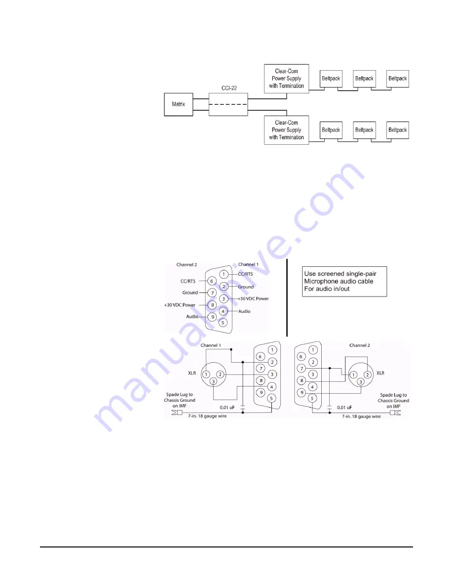
Figure 1-14: Connecting Easi-PiCo to Party Line Beltpacks

The "user" side of the CCI-22 for each channel is on a pair of DB-9M 
connectors on the rear of the interface frame. The diagram below shows the 
pinout of either one of these connectors. Both DB-9Ms are paralleled such that 
both party-line channels are available on each connector. 

It is possible to wire one DB-9 connector as channel #1, the second DB-9M as 
channel #2. This is the default wiring recommend for each map.

It is also possible to bring both channels out on a single DB9 connector.

Figure 1-15: Wiring for Easi-PiCo to Party Line Beltpacks

Summary of Contents for ECLIPSE EASI-PICO MATRIX

Page 1: ...ECLIPSE EASI PICO MATRIX U s e r G u i d e...

Page 2: ...Beach Drive Cambridge Research Park Cambridgeshire United Kingdom CB25 9TP Vitec Group Communications Room 1806 Hua Bin Building No 8 Yong An Dong Li Jian Guo Men Wai Ave Chao Yang District Beijing P...

Page 3: ...h one of the default maps to use 7 MAP 1 Basic Configuration 7 MAP 2 Party Line Configuration 8 MAP 3 IFB Configuration 9 MAP 4 Panels Configuration 10 Cable the system to Suit 10 Panel to Matrix 11 M...

Page 4: ...e maps contain IFB operation 43 Conferences Some maps contain Partyline conference operation 44 Groups some maps contain Group operation 44 10 Map Configurations 46 Basic Configuration 46 Party Line C...

Page 5: ...m the apparatus 11 Only use attachments accessories specified by the manufacturer 12 Use only with the cart stand tripod bracket or table specified by the manufacturer or sold with the apparatus When...

Page 6: ...nd thereby compliance with the requirement of Electromagnetic Compatibility Directive 2004 108 EC and Low Voltage Directive 2006 95 EC This device complies with Part 15 of the FCC Rules Operation is s...

Page 7: ...the front of the matrix The system has been designed to allow the user to setup the system without the need for any configuration software The matrix system also comes with 2 x partyline channels and...

Page 8: ...LINE AND MATRIX SYSTEMS The main difference between a partyline system and a matrix system is the level of control over the communications the systems can offer you Party Line Setup Figure 1 2 Party L...

Page 9: ...E a s i P i c o U s e r G u i d e 3 MATRIX SET UP Figure 1 3 Matrix or Point to Point Communications Configuration stored in memory Highly flexible any combination of people or groups...

Page 10: ...rface card Fits inside the IMF 102 Frame The FOR 22H connects the Easi PiCo intercom systems to two external 4 wire circuits Which could include two way radios microwave and satel lite links IFB camer...

Page 11: ...r a gooseneck microphone with a microphone headset selector switch and auto sensing when a gooseneck microphone is inserted integral speaker controls for side tone and microphone gains It includes des...

Page 12: ...or 2 5mm AUX headphone connector Headsets CC 26 Single ear headset The CC 26 is a single ear ultra lightweight headset with dynamic noise cancelling microphone element on a flexible boom Straight 5 5...

Page 13: ...USE The Easi PiCo is pre configured with the following maps MAP 1 Basic configuration MAP 2 Party Line configuration MAP 3 IFB configuration MAP 4 Panels configuration MAP 1 Basic Configuration This...

Page 14: ...o give the user the up to 8 party line channels in one system this gives the panel operators the option to speak to eight different party line rings individually or simultaneously This configuration c...

Page 15: ...B Interrupted Fold back channels one party line channel one 4 wire interface and a camera group which allows single or full group communications This configuration can support up to six panels IFB sou...

Page 16: ...designed to offer the most amount of panels with the four standard interfaces two party lines and two 4 wires This configuration can support up to twelve panels Figure 1 9 Panels Configuration System...

Page 17: ...E a s i P i c o U s e r G u i d e 1 1 PANEL TO MATRIX Figure 1 11 Panel to Matrix Connection...

Page 18: ...E a s i P i c o U s e r G u i d e 1 2 MATRIX TO EXTERNAL DEVICES VIA FOR 22 Figure 1 12 Connections to External Devices via FOR 22...

Page 19: ...E a s i P i c o U s e r G u i d e 1 3 MATRIX TO EXTERNAL PARTY LINE VIA CCI 22 Figure 1 13 Connection to Party Line via CCI 22...

Page 20: ...m below shows the pinout of either one of these connectors Both DB 9Ms are paralleled such that both party line channels are available on each connector It is possible to wire one DB 9 connector as ch...

Page 21: ...ix Audio Output from Matrix Audio Output from Matrix Audio Input into Matrix RS 422 Output from Matrix RS 422 Output from Matrix 1 2 3 5 6 7 1 2 6 7 8 4 3 4 5 8 RS 422 Output from panel RS 422 Output...

Page 22: ...operating parameters for the matrix system which includes all talk and listen paths for each connected interface belt pack or panel You can select and activate any of these maps directly from the Easi...

Page 23: ...m the PiCo s front panel since the last reset To exit the menu scroll to and select EXIT BASIC PANEL KEY OPERATION Making calls Talk keys Each configured Talk button red will be dim to indicate it has...

Page 24: ...ix on your loudspeaker automatically The listen key LED will lit bright YELLOW showing the key is active Release the key to stop monitoring A flashing DIM yellow key indicates that there is audio traf...

Page 25: ...Each of the four map configurations uses the GPO relay to close a contact whenever the RLY key is pressed on a panel When the contact is closed it completes an electronic circuit s signal path so that...

Page 26: ...Common RELAY 1 Normally Closed RELAY 1 Normally Open RELAY 2 Common RELAY 2 Normally Closed RELAY 2 Normally Open RELAY 3 Common RELAY 3 Normally Closed RELAY 3 Normally Open 30 VDC at 1 Ampere Commo...

Page 27: ...ck socket labeled RS 232 connects the matrix to an external computer This feature can only be used after the Easi PiCo is upgraded to an Eclipse PiCo Reset Button Pressing the reset button causes the...

Page 28: ...ower supply units One power sup ply unit can power an entire matrix the second unit provides a backup in case of an equipment failure In addition the two supplies have separate IEC connectors to AC ma...

Page 29: ...gure 1 24 Setup Enter Procedure The setup knob is used to navigate through the following screens by rotating the knob left and right to move the highlighted sections on the screen Once the section is...

Page 30: ...E a s i P i c o U s e r G u i d e 2 4 Figure 1 25 Easi PiCo Front Panel Menus...

Page 31: ...gle will first show a chequered pattern to indicate communications activity then will change to a solid light when the connected device is online and communicating with the matrix In addition a letter...

Page 32: ...After you have connected a GPO you can check whether or not a GPO is on directly from the front panel of the PiCo You can only toggle a GPO on or off directly from the Eclipse PiCo The front panel di...

Page 33: ...ll to the desired configuration map s checkbox 3 Press the setup enter knob to select the configuration An X appears in the configuration s checkbox when it is selected A screen appears asking you to...

Page 34: ...rough 8 Figure 1 32 Easi PiCo Output Level Screen Output level To adjust a port s outgoing audio levels 1 From the Output Level menu scroll to the PORT number When a port number appears onscreen that...

Page 35: ...er finally pushing the set knob to fix that specific character This is repeated until the passcode is entered Once the passcode is entered and saved the display will ask you whether you would like to...

Page 36: ...ck button will flash bright red The calling station s label will be temporarily assigned to the panel s Ans Back button These two conditions will continue until the call is answered or until the answe...

Page 37: ...a talk button If the talk is latched the microphone will remain on after the call Speaker This button toggles the front panel speaker between active bright yellow and inactive dim yellow If a headset...

Page 38: ...ease the Listen Call button Call Signals To activate call signals 1 Push and hold the Listen Call button until it is bright yellow at least 1 sec 2 Push the talk listen button programmed with a talk o...

Page 39: ...r a range of 0 to 20 dB Basic Panel Key operation Making Calls Talk keys Each configured Talk button red will be dim to indicate it has a programmed label When selected it will become bright RED to in...

Page 40: ...stination Push the correct key momentary to latch or push and hold for non latching key action You will hear all audio traffic from the destination port that is entering the matrix on your loudspeaker...

Page 41: ...pin female and male XLR connectors for looping the party line cables 4 pin male XLR to connect a headset Figure 1 36 RS 601 Beltpack Figure 1 37 RS 601 Beltpack Controls Talk Button 1 To talk on the...

Page 42: ...e beltpack circuitry to prevent incoming volume from exceeding a safe level Call Button 4 When you press the call button a call signal voltage is sent to all beltpacks and panels on the intercom line...

Page 43: ...ercom station if necessary Table 1 1shows the pin assignments for this connector Auxiliary AUX Headphone 10 Clear Com designed the auxiliary headset connector labelled AUX for use with the CC 25 Ultra...

Page 44: ...et Connector 11 You connect a headset to the beltpack at the 4 pin male XLR connector labelled headset The headset connector is always active and has priority if a second headset is connected to the a...

Page 45: ...ve a range of 13 dB they are normally set to the midrange position Send and Receive Null Adjustment In interfaces it is necessary to null minimize the leakage of send from return audio as much as poss...

Page 46: ...interact steps 3 and 4 will have to be repeated several times the test tone is minimized Continue adjustment until the tone is minimal If a deep null cannot be obtained it is likely that something is...

Page 47: ...io signal is being sent to the external device or system at a typical acceptable level The LED lights red when the audio output signal level is too high Recv Control The Recv Receive level controls af...

Page 48: ...E a s i P i c o U s e r G u i d e 4 2...

Page 49: ...audio to the destination IFB s can be used to interrupt background music on a PA system while someone is paging Normally in broadcasting presenters talents news anchors guest field reporters OB Vans...

Page 50: ...rmanently to the Party Line In the Easi PiCo basic configuration map port 8 is a fixed member of Party Line 1 This means that any panel that talks on this Party Line 1 will send audio to the beltpacks...

Page 51: ...e 4 5 The ALL key is group button made up of all 16 ports panels and interfaces The GPE key is group button made up of all the interface ports The IFB map has a Camera Group button The CAMS key is gro...

Page 52: ...guration Panels Configuration BASIC CONFIGURATION This is a straightforward configuration that gives the user access to the four standard Interfaces along with the possiblity of adding up to 4 more ex...

Page 53: ...E a s i P i c o U s e r G u i d e 4 7 Figure 2 43 ICS 1016E Panel in Basic Configuration Figure 2 44 ICS 1008E Panel in Basic Configuration...

Page 54: ...E a s i P i c o U s e r G u i d e 4 8 Figure 2 45 Basic Configuration Cross Point Map Figure 2 46 Basic Configuration Ports...

Page 55: ...to give the user the up to 8 party line channels in one system this gives the panel operators the option to speak to eight different party line rings individually or simultaneously This configuration...

Page 56: ...E a s i P i c o U s e r G u i d e 5 0 Figure 2 48 ICS 1016E for Party Line Configuration Figure 2 49 ICS 1008E for Party Line Configuration Figure 2 50 Party Line Configuration Cross Point Map...

Page 57: ...E a s i P i c o U s e r G u i d e 5 1 Figure 2 51 Party Line Configuration Ports...

Page 58: ...d a TV studio set up with four IFB Interrupted Fold back channels one party line channel one 4 wire interface and a camera group which allows single or full group communications This configuration can...

Page 59: ...E a s i P i c o U s e r G u i d e 5 3 Figure 2 54 ICS 1008E for IFB Configuration Figure 2 55 IFB Configuration Cross Point Map...

Page 60: ...E a s i P i c o U s e r G u i d e 5 4 Figure 2 56 IFB Configuration Ports...

Page 61: ...signed to offer the most amount of panels with the four standard interfaces two party lines and two 4 wires This configuration can support up to twelve panels Figure 2 57 Panels Configuration This dia...

Page 62: ...E a s i P i c o U s e r G u i d e 5 6 Figure 2 59 ICS 1008E for the Panels Configuration Figure 2 60 Panels Configuration Cross Point Map...

Page 63: ...E a s i P i c o U s e r G u i d e 5 7 Figure 2 61 Panels Configuration Port Map...

Page 64: ...i PiCo passcode 1 x ECS configuration software The upgrade gives the user access to all 36 ports at the rear of the PiCo matrix note the ports 17 36 will be plugged in Easi PiCo mode these are easily...

Page 65: ...ap configurations key allocation on panels routing and control of external interfaces The Easi PiCo upgrade Licence can be purchased from your local dealer distributor or by visiting the ClearCom webs...

Page 66: ...o the talent The normal audio returns once the person stops keying to the talent Party line In a party line system all of the people on a given channel can talk and listen to each other simultaneously...

Page 67: ...E a s i P i c o U s e r G u i d e 6 1...

Page 68: ...E a s i P i c o U s e r G u i d e 6 2...

Page 69: ...s and spare parts have a limited warranty of one year UHF wireless IFB products have a limited warranty of one year UHF wireless intercom systems have a limited warranty of three years All other Clear...

Page 70: ...ica Canada Mexico Caribbean US Military Tel 1 510 337 6600 Email customerservicesUS vitecgroup com Asia Pacific South America Tel 1 510 337 6600 Email customerservicesAPAC vitecgroup com VGC has the r...

Page 71: ...CUSTOMER HEREUNDER SHALL NOT UNDER ANY CIRCUMSTANCES EXCEED THE COST OF REPAIRING OR REPLACING ANY PART S FOUND TO BE DEFECTIVE WITHIN THE WARRANTY PERIOD AS AFORESAID This warranty does not cover an...

Page 72: ...W A R R A N T Y i v...

Page 73: ...r All Pnl1 Pnl2 PL1 PL2 PL3 PL4 ICS1008E Ans Pnl3 Pnl4 Pnl5 PL1 PL2 PL3 PL4 IFB Config Clear All Pnl1 Pnl2 Ext1 IFB1 IFB2 PL IFB3 IFB4 Cams GPE Pnl6 Rly ICS1016E Ans Pnl3 Pnl4 Pnl5 Ext1 IFB1 IFB2 PL I...

Reviews: