background image

8

HKM 700 | 1.01

Operation


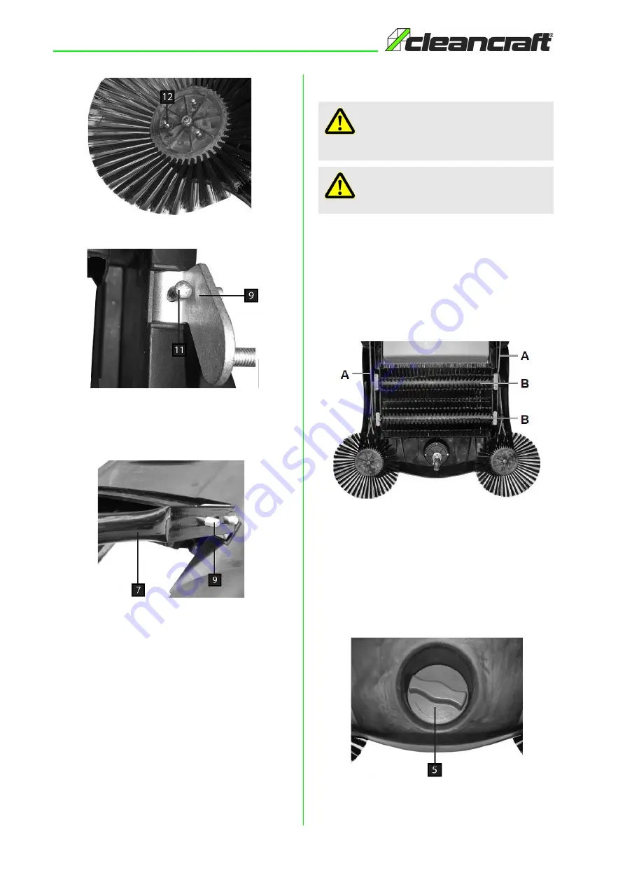
Fig. 4: Adjustment of the feed-in brush


Fig. 5: Adjustment of the push bar

Step 4: Put the bottom section of the push bar (Pos. 7, 

Fig. 6) onto the push bar mounts (Pos. 9, Fig. 6) 
and secure with he two adjustment nuts.


Fig. 6: Adjustment of the bar

Step 5: Slide the top section of the push bar onto the 

bottom section of the push bar (Pos. 7, Fig. 6) 
and secure with two adjustment nuts, two as-
sembly screws and the washers.

9

Operation

When the mechanical sweeper is pushed, the feed-in 
brushes and the pick-up brushes (Pos. B, Fig. 7) are set 
in rotation by the belt drives (Pos. A, Fig. 7).

The rotating feed-in brushes (Pos. 4, Fig. 3) sweep the 
dirt to the centre. The two counter-rotating pick-up brus-
hes (Pos. B, Fig. 7) convey the dirt into the dirt container 
(Pos. 4, Fig. 3) 


Fig. 7: Functional principle

9.1 Adjusting the Feed-in Brushes

Use the setting screw (Pos.5, Fig. 8) to steplessly adjust 
the height of the feed-in brushes  as required. Turn the 
setting screw clockwise to increase the distance to the 
ground. Turn the setting screw counter clockwise to de-
crease the distance to the ground.


Fig. 8: Adjusting the feed-in brushes

WARNING!

For the ensure safe operation must regularly clean 
the dirt container.

ATTENTION!

Do not use the device in wet conditions!

Summary of Contents for HKM 700

Page 1: ...HKM 700 Manual Sweeper Operating Instructions HKM 700 HKM 700...

Page 2: ...ntent 1 Introduction 3 1 1 Copyright 3 1 2 Customer service 3 1 3 Limitation of liability 3 2 Safety 3 2 1 Symbol explanation 3 2 2 Obligations of the operating company 4 2 3 Requirements to staff 5 2...

Page 3: ...urther 1 3 Limitation of liability All information and notes in these operating instructions were summarised while taking applicable standards and rules the state of the art technology and our long te...

Page 4: ...by her correspond to the current status of the regulations and must adapt these if necessary The operating company must unambiguously reg ulate and determine the responsibilities for instal lation ope...

Page 5: ...equipment is explained in the following paragraph 2 5 General safety regulations Please note the following Please note the following safety notes to avoid mal functions damage or physical injury Perso...

Page 6: ...liability for any constructional or technical modifications carried out on the electric manual sweeper Any claims due to damages because of not intended use are excluded 3 1 Misuse 3 2 Residual risks...

Page 7: ...a dry frost free environment 7 Description of the device Fig 3 Ger tebeschreibung HKM 700 1 Push bar 2 Adjustment nut for push bar 3 Dirt container 4 Sweeping brush 5 Setting screw for adjusting the h...

Page 8: ...s Pos B Fig 7 are set in rotation by the belt drives Pos A Fig 7 The rotating feed in brushes Pos 4 Fig 3 sweep the dirt to the centre The two counter rotating pick up brus hes Pos B Fig 7 convey the...

Page 9: ...rasives Remove debris such as leaves twigs etc from the brushes Regularly check the drive belts for proper tight ness and elasticity Store the sweeper indoors in a dry place that is pro tected from du...

Page 10: ...of spare parts Type of device Item No Position No Year of construction Quantity Required mode of dispatch mail freight sea air express Address of dispatch Spare part orders which do not include the a...

Page 11: ...parts drawing In case of service the following drawing shall help to identify the necessary spare parts If necessary send a copy of the parts drawing with the marked components to your authorised dea...

Page 12: ...www cleancraft de...

Reviews: