


GUIDELINES FOR USED OIL TANKS:
(1) The tank installation must comply with NFPA 30 and NFPA 31 fire codes.
(2) The tank should be installed on a slight slope with a drain on the low end to allow sludge
and water to be removed from the bottom of the tank.
(3) All oil lines must be constructed of copper, steel, or brass components. DO NOT use
rubber, plastic, or any other inappropriate material for oil lines.
(4) Be sure to follow all instructions for tank installation in the Owner’s Manual.
6
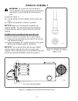
WARNING:
To avoid serious injury or death, only store petroleum based substances
in the oil supply tank (the following are approved fuels):
(1) Used Crankcase Oil
(2) Used Automatic Transmission Fluid (ATF)
(3) Used Hydraulic Oil
(4) #2 Fuel Oil (Diesel Fuel)
DO NOT put flammable or corrosive substances such as gasoline, chlorinated solvents,
paint thinner, or any other unsafe substance in the oil supply tank.
WARNING:
To avoid serious injury or death, do not weld or allow open flames within
35 feet of the used oil supply tank.
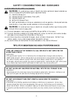
SAFETY CONSIDERATIONS AND GUIDELINES
TIPS FOR MAINTAINING HIGH PERFORMANCE
DO NOT ALLOW ANY UNAPPROVED MATERIAL INTO THE OIL STORAGE TANK.
Explana on:
Material placed in the oil storage tank will eventually be delivered to the burner. An freeze and
water will not ignite and will cause the hea ng equipment to shut down.
DO NOT USE EXHAUST FANS THAT CREATE A VACUUM IN THE BUILDING.
Explana on:
A backdra at the hea ng equipment will damage cri cal burner components. If your shop
requires exhaust fans there must be adequate make up air so that the furnace can maintain a
proper natural dra . If there is insuffi
cient make up air, install make up air louvers or use a relay
to open the wall thermostat circuit to ensure the burner does not fi re when an exhaust fan is in
use.
TURN OFF POWER TO THE BURNER IF A CALL FOR HEAT IS NOT EXPECTED FOR
MORE THAN A WEEK.
Explana on:
If the green power light is “on” at the burner, the oil temperature is being maintained by the
200W heater element. If this oil temperature is maintained over a long period of me (like over
the summer months) without a call for heat, the nozzle adapter heater block is more likely to
accumulate carbon build up which may cause a plugged nozzle. Flip the breaker “off ” at the panel
or turn the Burner Power Switch “off ” located on the junc on box on top of the unit.
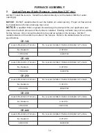
Summary of Contents for CE-140
Page 50: ...50 NOZZLE ADAPTER HEATER BLOCK ASSEMBLY 2 3 19 5 7 8 15 9 17 14 18 16 13 1 4 6 10 11 12 ...
Page 52: ...52 MANIFOLD BLOCK ASSEMBLY 8 6 2 1 4 17 3 9 5 7 12 13 14 15 16 18 19 11 10 ...
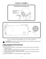
Page 58: ...58 3 4 6 1 2 5 CE 140 180 BLOWER ...
Page 62: ...62 2 3 4 5 6 1 CE 250 BLOWER ...
Page 66: ...66 CE 330 BLOWER 12 8 7 4 13 1 2 3 5 6 9 10 11 ...
Page 70: ...70 CE 440 BLOWER 12 8 7 4 13 1 2 3 5 6 9 10 11 ...


