


-
8
-
Read and follow these instructions in the event you
have to replace or re-assemble components of your
furnace.
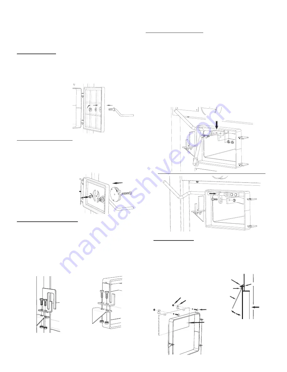
DOOR HANDLES
Insert door handle into door. From rear side of door,
place a 1/2” washer over the threaded part of the
handle, then attach the lock nut. Tighten the nut, then
back off 1/4 turn to allow free operation of the handle.
Follow these same directions for the ash door handle
assembly.
(2) Door Handle
(2) 1/2” Washer
(2) 1/2” Lock Nut
ASH DOOR SPIN DRAFT
Screw the spin draft onto the 3/8” x 2-1/2” carriage
bolt. Then screw the spin draft and bolt into the ash
door allowing approximately 1/2” of the bolt to stick
through the back side of the ash door. Secure the bolt
in place with the 3/8”-16 lock nut.
(1) Spin Draft
(1) 3/8-16 Carriage Bolt
(1) 3/8-16 Lock Nut
FUEL & ASH DOOR LATCH
With two 1/4-20 x 3/4 hex bolts each, attach the door
latches to the door latch mounting brackets on the
left side of the door frames as illustrated. The slots in
the brackets and latches are for door seal adjustment.
Make the proper adjustments, then tighten the nuts.
The door’s gasket should be snug against the door
frame on the furnace.
Feed Door
Illustration
Ash Door
Illustration
(1) Feed Door Latch
(1) Ash Door Latch
(4) 1/4-20 x 3/4 Hex Bolt
(4) 1/4-20 Kep Nut
BRACKET
SHAKER GRATE HANDLE
Insert the Shaker Rod into the hole on the ash door
frame as shown. Then attach the Shaker Bracket to the
front of the furnace using two 1/4-20 x 3/4” Hex Bolts
and two 1/4-20 Lock Nuts. Next, insert the shaker Rod
into the bracket and attach to the shaker grate bar
using the 1/4-20 x 1” Hex Bolt and a 1/4-20 Lock Nut. The
bolt and nut retaining the shaker bar and rod should be
left loose to allow free movement of the grates.
(1) Shaker Rod
(1) Shaker Bracket
(1) 1/4-20 x 1” Hex Bolt
(2) 1/4-20 x 3/4” Hex Bolt
(3) 1/4-20 Lock Nut
FRONT
SMOKE CURTAIN
SMOKE CURTAIN
CLIP
NUT
BOLT
1/4-20 NUT
SMOKE CURTAIN
CLIP
1/4-20 x 1-1/4
CARRIAGE BOLT
SMOKE CURTAIN
SMOKE CURTAIN
Using two 1/4-20 x 1-1/4” Carriage bolts, the smoke
curtain clips and two nuts, attach the smoke curtain
in place above the Fuel Feed Door as shown below.
After installation, the smoke curtain should swing
freely back into the furnace.
(1) Smoke Curtain
(2) Smoke Curtain Clips
(2) 1/4-20 x 1-1/4 Carriage Bolt
(2) 1/4-20 Kep Nut
Furnace Assembly Instructions
Summary of Contents for 1600EF
Page 15: ... 15 Wiring Diagram SERVO MOTOR ...
Page 16: ... 16 Parts Diagram ...


