10
English
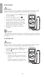
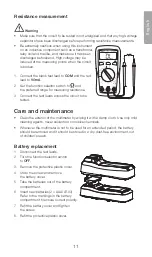
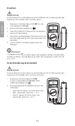
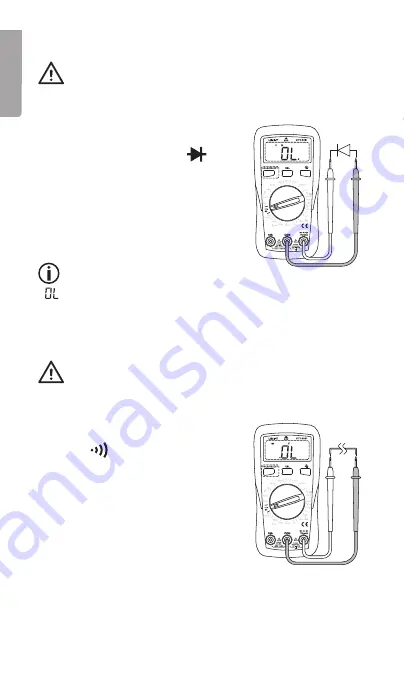
Diode testing
Warning
Make sure that the circuit to be tested is not energised and that any high-voltage
capacitors have been discharged before performing diode measurements.
1. Connect the black test lead to
COM
and the red
test lead to
VΩmA
.
2. Set the function selector switch to
.
3. Press the [ HOLD/SELECT ] button to toggle
between buzzer mode and diode test mode.
4. Connect the black test lead to the cathode
(negative end) and red test lead to the anode
(positive end) of the diode to be tested.
5. Read the forward voltage drop value from
the display.
Information
If
is displayed, the diode is either open or the polarity is reversed. Try reversing
the polarity of the diode. The normal value for a P–N junction is about 500–800 mV
(0.5–0.8 V).
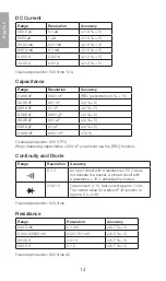
Continuity test
Warning
Make sure that the circuit to be tested is not energised and that any high-voltage
capacitors have been discharged before performing continuity tests.
1. Connect the black test lead to
COM
and the red
test lead to
VΩmA
. Set the function selector
switch to
.
2. Connect the ends of the test leads to the ends of
the cables to be tested.
-
No break in the cable: The buzzer sounds
continuously if the resistance in the cable is
≤ 10 Ω.
-
A break in the cable: The buzzer does not
sound if the resistance in the cable is > 50 Ω.


