Clarke Woodworker CMS254 Operating & Maintenance Instructions Download Page 12

Allow the blade to reach full speed. If any unusual sounds or vibrations
occur, release the Trigger immediately and investigate the cause.

When satisfied, move the Head Release Lever, (C fig.7 and also shown in
fig.10), sideways with the fingers of your right hand, and gently lower the
head so that the blade comes into contact with the workpiece. Do not
force the blade, a light pressure is all that is required.

You will notice that to provide maximum safety, the blade is not exposed
at any time, and the guard rises automatically as the blade is lowered.
Nevertheless, NEVER treat the machine with indifference, and NEVER be
casual with your approach.

To switch off, release the Trigger whilst still maintaining full control of the
head.

NOTE: The Head should rise under spring pressure, gently. If the movement
is too rapid or conversely, too sluggish, spring tension needs to be adjusted.

Refer to ‘Adjustments on page 16.
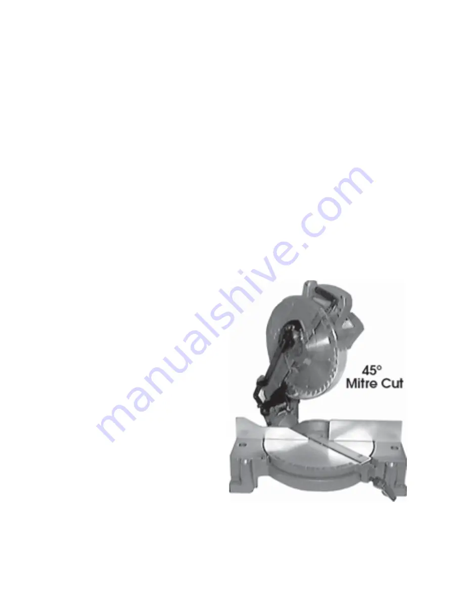
B. Mitre Cutting

This is a cross cutting operation,
except that the saw blade is set
at an angle to the work, but
remains perpendicular to the
table. The head is mounted on
the table which is free to rotate
by up to 45°, left and right.

To set the required mitre angle
unscrew the Table Lock Handle
and rotate the Table, with the
Head and saw blade, to the
desired position, lining up the
angle on the scale, with the
pointer shown in Fig. 3 on page
9. Lock the Table in position with
the Locking Handle.

The procedure for cutting is the
same as that for cross cutting.

For convenience, positive stops are provided at various angles. These are:

Zero (90°), 22.5° and 45°

Fig. 8

12

Summary of Contents for Woodworker CMS254

Page 1: ...OPERATING MAINTENANCE INSTRUCTIONS CMS254 COMPOUND MITRE SAW 0604...

Page 2: ...ead Lowered 365x345x270mm Dimensions Head Raised 365x345x410mm Blade size Fitted 254mm 40T 16mm Bore Noise level 110dB at 1M Vibration Level 22 2m s Normal Load Weight 10 7kg unpacked Part Number 6500...

Page 3: ...your receipt as proof of purchase This guarantee is invalid if the product is found to have been abused or tampered with in any way or not used for the purpose for which it was intended Faulty goods s...

Page 4: ...n shadow 4 CHECK for DAMAGE Before using the machine any damaged part such as a guard etc should be checked to ensure that it will operate properly and perform its intended function Check for alignmen...

Page 5: ...NE IN TOP CONDITION Keep tools sharp and clean for the best and safest performance Follow maintenance instructions 21 DON T OVERREACH Keep your proper footing and balance at all times For best footing...

Page 6: ...e power OFF and disconnected from the supply 9 DO NOT operate the machine with the guards removed They must all be in place and securely fastened when performing any operation 10 Use ONLY approved rep...

Page 7: ...coloured BLACK If this appliance is fitted with a plug which is moulded onto the electric cable i e non rewirable please note 1 The plug must be thrown away if it is cut from the electric cable There...

Page 8: ...PRINCIPAL PARTS OF THE SAW Fig 1 82...

Page 9: ...the dust bag provided is attached If required a vacuum extraction device may be used which will provide fast and efficient removal of sawdust The extraction device may be used continuously or intermit...

Page 10: ...e working in your own shadow Four holes are provided in the base shown at A fig 3 so that the machine may be bolted permanently to a workbench for added stability Alternatively it may be bolted to a p...

Page 11: ...lso ensure the table is locked using the table locking handle NOTE If the workpiece is not entirely straight ensure that the portion at either side of the intended cut rests firmly against the table a...

Page 12: ...still maintaining full control of the head NOTE The Head should rise under spring pressure gently If the movement is too rapid or conversely too sluggish spring tension needs to be adjusted Refer to...

Page 13: ...ording to the scale adjacent to the pivot point and shown in fig 9 Lock the head in position by tightening the Bevel Locking Handle The 45 adjuster is factory set so that when the Head is tilted to it...

Page 14: ...ndling the saw blade The tips are extremely sharp and careless handling could result in severe personal injury MAINTENANCE 1 With the Machine disconnected from the mains supply and the Cutting Head in...

Page 15: ...ng the motors end cover andpull off the cover 2 With a pair of long nose pliers pull out each brush holder as shown in fig 14 and disconnect the push on connector 3 Insert the new brush with spring Fi...

Page 16: ...n slacken off the adjuster locknut at A screw the adjuster in or out as the case may be until the blade is exactly square keeping light pressure on the head to keep it in contact with the adjuster scr...

Page 17: ...acken the adjuster locknut shown at B and screw the adjuster in or out as the case may be to acquire the correct angle and when satisfied lock the adjuster with the locknut d Cutting Head Spring Tensi...

Page 18: ...PARTS DIAGRAM 18...

Page 19: ...lat Washer DQ412011011 33 Pan Hd Screw DQ410131020 34 Table Insert DQ0352410201 35 Table DQ0352410104 36 Pad DQ0301020219 37 Table Locking Handle DQ0301020214 38 Pad DQ0351310302 39 Rivet DQ410503001...

Page 20: ...ring DQ0351310904 98 Trigger DQ0351310208 99 Rubber Pin DQ414060003 100 Ball Bearing DQ420010502 101 Power Cord DQ0351320701 102 Terminal Block DQ451050002 103 Pan Hd Screw DQ410251001 104 Ext Tooth W...

Page 21: ...23...

Reviews: