background image

-12-

-7-

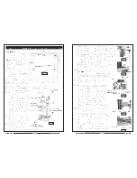
Electrical  Circuit  Diagram  230v  50Hz

Maintenance 

(Figures in brackets refer to parts diag page 11)

The amount of maintenance depends on the amount of use the machine gets, however

it is important to carry out routine maintenance to prevent premature wear and shortening

the life of the machine.
1. Inspect and clean all non painted surfaces, lubricate using a light machine oil, Do

Not over lubricate, oil can be applied to the worktable and column etc, using a soft

oil soaked cloth.

2. Inspect and clean all moving parts, Lubricate using machine oil, check for smooth

operation.

3. Inspect the machine for signs of wear or damage, any faults should be rectified

before  continuing.

4. Occasionally remove and inspect the motor brushes for even wear etc. Brushes should

wear evenly and not show signs of burning or grooves etc. Consider replacing both

brushes when one brush is 50% worn, (new brush = 15mm in length).

5. Check all supporting bolts etc are tight.

With use, play may develop between the following components.

a. Column (102) - Spindle Box (24).
b. Base (74) - Saddle (114).
c. Saddle (114) - Worktable (105).

Any play can be removed by adjusting the offending part i.e., if excessive play is found

between the base and saddle, proceed as follows;
Tools required = 7mm spanner and small flat bladed screwdriver and 3mm allen key.
1. Loosen locking screw (71), using 3mm allen key.
2. Loosen 4 locknuts (73), using 8mm spanner.
3. Using flat bladed screwdriver back off all four adjusting screws (72), approximately

one full turn.

4. The saddle can now be removed from the base to enable cleaning of the friction

surfaces before adjustment, to do this, turn the crossfeed handwheel anticlockwise

until the saddle comes off the end of the leadscrew. Carefully slide the saddle assembly

off the base, taking care not to drop it.

5. Clean all friction surfaces of all oil and dirt etc using a commercial degreaser and soft

cloth, observing the manufacturers recommendations at all times.

6. Lightly lubricate all friction surfaces and reassemble in reverse order.
7. Position the saddle in the centre of the base.
8. Turn the crossfeed handwheel backwards and forwards, at the same time using small

flat bladed screwdriver, gently, starting on one of the centre adjusting screws, tighten

until resistance is felt on the handwheel, turn adjusting screw back one ¼ turn,

handwheel should move freely again, holding the screw with screwdriver, gently nip

the  locknut.
Repeat procedure for the other centre screw, when finished re-check adjustment for

previously adjusted screw, if any further adjustment of that screw is required, it will be

necessary to re-check the second adjusting screw again. Once both centre adjusting

screws are OK and the locknuts are secured, the same procedure can the be applied

to the end screws in turn. When finished adjusting, check the full travel of the saddle

ensuring there is no play, if any play is found, then further adjustment must be carried

out until handle turns freely with no play between the saddle and base.
The above procedure applies to all three moving assemblies equally, other than

perhaps a different size spanner may be required.

Summary of Contents for Metalworker CMD10

Page 1: ...OPERATING MAINTENANCE INSTRUCTIONS 0403 Part No 6460200 MODEL No MODEL No CMD10 Part No 7610850 MICRO MILLING DRILLING MACHINE MICRO MILLING DRILLING MACHINE ...

Page 2: ... 1 18 NOTES ...

Page 3: ...f others around you and is also to help you achieve a long and trouble free service from your new tool PARTS SERVICE TEL 020 8988 7400 or e mail as follows PARTS Parts clarkeinternational com SERVICE Service clarkeinternational com CLARKE GUARANTEE This CLARKE product is guaranteed against faulty manufacture for a period of 12 months from the date of purchase Please keep your receipt as proof of p...

Page 4: ...10123 Fuse Box 1 124 SG10124 Power Indicating Lamp 1 125 SG10125 Forward Reverse Switch 1 126 SG10126 Electricity Label 1 127 SG10127 Screw ST2 9 x 6 5 4 128 SG10128 Power Cord Plug 1 129 SG10129 Caution Label 1 131 SG10131 Technical Data Label 1 132 SG10132 Chuck 1 133 SG10133 Allen Wrench S 3 6 1 ea 134 SG10134 Spanner 5 5 x 7 8 x 10mm 1 ea 135 SG10135 Socket Head Wrench D38 42 1 136 SG10136 Oil...

Page 5: ...an for the best and safest performance Follow maintenance instructions 10 ALWAYS handle with extreme care do not carry the tool machine by its electric cable or yank the cable to disconnect it from the power supply 11 ALWAYS ensure the switch is off before plugging in to mains Avoid accidental starting 12 ALWAYS concentrate on the job in hand no matter how trivial it may seem Be aware that acciden...

Page 6: ...ghtenining or loosening the chuck 10 NEVER Change from high to low speed and vice versa whilst the machine is still running always ensure the machine has come to a complete stop before doing so 11 NEVER change from forward to reverse and vice versa whilst the machine is still running always ensure the machine has come to a full stop before doing so Additionally please keep these instructions in a ...

Page 7: ...onductor size should also be at least the same size as that on the machine or larger When using a cable reel always unwind the cable completely 3 Should you wish to replace a detachable fuse carrier ensure that the correct replacement is used as indicated by marking or colour code 4 Replacement fuse covers can be obtained from your local dealer or most electrical stockists IMPORT ANT If a cable ex...

Page 8: ... 72 approximately one full turn 4 The saddle can now be removed from the base to enable cleaning of the friction surfaces before adjustment to do this turn the crossfeed handwheel anticlockwise until the saddle comes off the end of the leadscrew Carefully slide the saddle assembly off the base taking care not to drop it 5 Clean all friction surfaces of all oil and dirt etc using a commercial degre...

Page 9: ...iate method e g T bolts and clamps or vice etc Insert the cutter to be used into the chuck etc and tighten securely Only use good quality cutters with the correct form and sharpness etc Ensure the chuck guard is in place and securely fixed For added accuracy if you are only for instance using the cross feed when cutting ensure all other axis are locked vertical and horizontal Select the correct cu...

Page 10: ...ns whilst supporting the drill chuck with one hand gently using a plastic mallet or similar DO NOT USE HAMMER apply a swift blow to the top of the draw bar this should cause the chuck to fall if not repeat with plastic hammer applying a little more force Once the chuck is free continue to support with one hand and unscrew the draw bar completely until the chuck can be removed store removed parts s...

Reviews: