


11
UNPACKING & PREPARING FOR USE
On receipt, carefully unpack the lathe. Inspect to ensure that no damage was
suffered in transit and all parts are accounted for. Should any damage be apparent,
or parts are missing, please contact your Clarke dealer immediately.
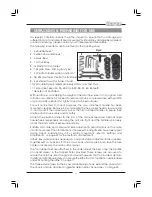
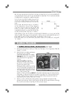
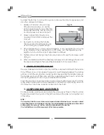
The following loose items are to be found in the packing case.
1. 4 x Rubber Feet.*
2. 4 x M6 Pan Head Scews.*
3. 4 x Hex. Keys.
4. 1 x Chuck Key.
5. 1x Plastic Oil Container.*
6. 1 x Spare Fuse - 2amp, glass type.*
7. 2 x Plastic Handles w/Nuts and Bolts.*
8. No.2 Morse Taper Centre (for Tailstock).
9. 3 x External Jaws (for 3-Jaw Chuck).
10.2 x Double Open Ended Spanners 8x10mm and 14x17mm.
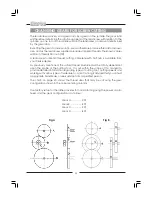
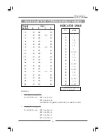
11.1 x Gear Set. Sizes: 30, 35, 40, 40, 45, 50, 55, 57, 60, 65 Teeth.
* denotes not illustrated.
With assistance, considering the weight of the machine, raise it on to a good solid
surface or workbench. Proceed to remove all traces of preservative with paraffin
or good quality solvent, and lightly oil all machined surfaces.
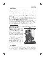
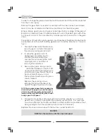
You will notice that, for transit purposes, the cross slide feed handle has been
mounted in reverse. Remove it, by unscrewing the hex. socket head screw securing
it, and mount it the correct way round. Then turn all feed handles to ensure they
are free and move evenly and smoothly.
Attach the plastic handles to the rims of the manual feed and tailstock feed
handwheels respectively, ensuring the nuts are tight and the handles spin freely
about the bolts, without excessive end play.
Saddle, cross-slide and compound slide adjustments are all factory set to ensure
smooth movement in both directions. If however the adjustments have been upset
during transit, indicated by stiff or erratic movement, refer to ‘Settings and
Adjustments’ on page 22 for the methods of adjustment.
All hex. keys and spanners necessary to carry out various adjustments are supplied,
together with a chuck key for the 3-Jaw chuck and a spare 2 Amp fuse. The fuse
holder is located on the main control panel.
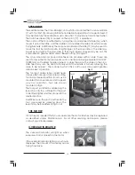
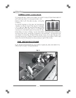
The four rubber feet are attached to the underside of the bed, using the four M6
pan head screws, in the tapped holes provided. These screws are also used to
secure the chip tray. We strongly recommend however, that to provide maximum
stability and additional safety, you secure the lathe to a firm foundation as described
under ‘Mounting the lathe’ on page 11.
The three external jaws for the 3-Jaw self centering chuck, extend the capacity of
the chuck, and are discussed in greater detail under ‘Accessories’ on page 24.
11
8
9
10
3
4
Fig. 4
Summary of Contents for MetalWorker CL300M
Page 1: ...1 OPERATING MAINTENANCE INSTRUCTIONS 300mm VARIABLE SPEED METAL LATHE Model No CL300M 1008...
Page 4: ...4...
Page 29: ...29 PARTS DIAGRAM...
Page 30: ...30 WIRING DIAGRAM...
Page 31: ...31 NOTES...
Page 32: ...32...


