


8
requirements are indicated on the AC
electrical wiring. Connect the supplied heater
connection wire directly to a customer
supplied electrical junction box.
Supply
wiring should never be routed through the
engine gauge panel
. Severe damage to
critical engine control components could
result.
8)
Connect exhaust system to flexible
connection on the engine. The exhaust
system plumbing must be supported by the
building structure and not the engine. The
exhaust flexible connection is provided only
for the purpose of thermal expansion and
vibration isolation, not for misalignment or
directional change.
9)
Make electrical DC connections between the
engine gauge panel terminal strip (if
supplied) and the controller per the controller
manufacturer’s instructions.
10)
Fill batteries with electrolyte per battery
manufacturer’s instructions. Connect cables
between engine and batteries only after
electrolyte is installed. Refer to the wiring
diagram inside the engine gauge panel cover
(if supplied), or appropriate wiring diagram,
for correct positive and negative connections.
Connect negative cables directly to the
ground stud. Connect each positive cable to
the starter contactors.
11)
Note: Clarke Operation and Maintenance
Instructions Manual and Clarke parts
illustration pages are furnished with the
engine.
12)
IMPORTANT! In order to obtain prompt
Warranty Service, this engine
must
be
registered to the final installation name and
address. To register this engine, go to
www.clarkefire.com
and select Warranty
Registration.
2.4
COUPLING ALIGNMENT INSTRUCTIONS
Various types of couplings or drive shafts could be
used with these engines. Refer to coupling
manufacturer’s alignment procedure.
2.5
WEEKLY TEST
An experienced operator should be present during the
weekly test.
NOTE: This engine is designed to operate at rated
load conditions. For testing purposes the engine can
be run at lower load (lower flow) conditions.
Running times in any one period should not exceed
30 minutes maximum.
Before starting the engine make sure of the
following:
1)
The operator has free access to stop the
engine in an emergency.
2)
The plant room ventilation ducts are open
and the engine has good access for air.
3)
All the guards are in position and, if not, for
whatever reason, any rotating parts will be
free and clear without restriction.
4)
Battery covers are in place and there is
nothing on top of or touching the engine,
which is not part of the original supply
specification.
5) Air Cooling: The air supply for cooling and air
ducting to outside of the building have no
restrictions.
When engine is running make sure that the oil
coolant temperature, oil pressure and raw cooling
water flow are within the limits specified on the
relevant Installation & Operation Data Sheet.
If the coolant temperature is excessive, check the
cooling loop strainer and proper operation of water
solenoid valve.
2.6
STARTING/STOPPING THE ENGINE
2.6.1 Special Notes to Equipment Installer of an
LPCB Approved (LPS1239) Engine Model: Any
device fitted to the engine or controller, which could
prevent the engine starting automatically, shall return
automatically to the normal position after manual
application. The electrical fuel shutoff actuator shall
be connected to an Engine Stop button on the main
pump controller.
The main pump controller shall de-energize the start
motor when the engine has achieved 700-1000 rpm.
2.6.2
To Start Engine
Use main pump controller for starting. Follow
instructions provided by controller manufacturer.
On LPCB engines, use main pump controller for
starting and stopping the engine. Should the main
pump controller become inoperable, the engine can
be manually started from the engine gauge panel.
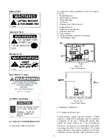
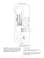
For manual starting of an engine with a gauge panel.
(Refer to
Figure #9A
): Lift and hold
MANUAL


