6
ASSEMBLY
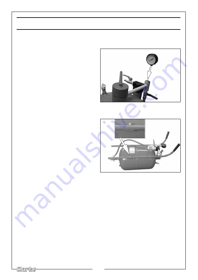
FIT THE PRESSURE GAUGE TO THE TANK
1.
Fig 1
Screw the pressure gauge onto
the sandblaster as shown in Fig 1.
• PTFE Tape may be required to
give a perfect seal.
FIT THE HANDLE BARS TO THE TANK
1.
Fig 2
Lay the tank on a flat level surface
(such as a workbench or table
top), with the handlebar mounting
brackets facing up, as shown in Fig
2.
• Handlebars are labelled “LEFT”
and “RIGHT.”
2. Align the holes in the left
handlebar with the handlebar
mounting brackets on the left side
of the tank.
3. Place a washer onto each of the four handlebar mounting screws. Insert a
screw through each of the holes in handlebar and mounting brackets,
4. Place a nut onto each of the screws and firmly tighten in place with a
wrench.
5. Repeat steps 2-4 for the right handlebar.
Summary of Contents for CPSB200
Page 15: ...15 EXPLODED DIAGRAM PARTS LIST ...
Page 17: ...17 DECLARATION OF CONFORMITY ...
Page 18: ...18 NOTES ...
Page 19: ...19 NOTES ...
Page 20: ......


