


Service Manual-CA60 34 Scrub System DISC(CA60 20D/20TD) 50
34 Scrub System, Disc (CA60 20D/20TD)
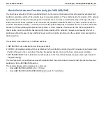
Functional Description
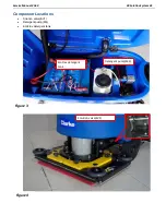
The disc brush system can be started by the operator.
The disc brush turns counter-clockwise.
The rotating brush system cleans the surface of the floor.
The main component of the brush system is the deck
where the brush or the pad holder with pad suitable for the
type of surface to be cleaned is installed.
Brush rotation occurs only when the brush motor (M1) is
driven by one of the two handle switches. The brush
system uses the solution to wash the floor.
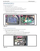
In case of brush motor overload, the circuit breaker (F1)
stops the brush to prevent continuous overload.
To start scrubbing again after a brush stop due to
overload, turn the machine off, reset the circuit breaker
(F1), turn the machine on.
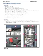
To work properly, the brush motor (M1) needs the fol-
lowing:
Brush function on
One of the two handle switches is pressed
Battery level not in critical condition with flashing
segments.
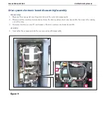
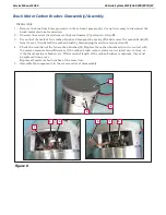
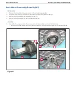
Brush Release System
To release the brush from its hub, the brush motor starts
up and then stops rapidly.
The brush’s inertia thus causes
it to disengage from the hub. First the contactor K1 turn
on, two seconds later, the release Relay in E1 will on,
cause J4 short to J5. Then K1 turn off. When the K1 turns
off, both sides of the motor are connected to battery
positive which causes the brush motor to stop rapidly.
1
1
2
2
3
3
4
4
5
5
6
6
7
7
8
8
D
D
C
C
B
B
A
A
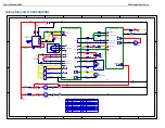
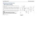
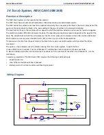
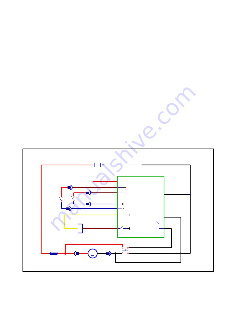
Scrub System Disc Wiring Diagram (CA60 20D/CA60 20TD )
F1
Circuit Breaker 30A
J1-11
K1
Brush Contactor
M
M1
Brush Motor
J1-12
+24V
E1 Main Control Board
K1
+
-
C8a
C8b
B-
Release Enable Relay
J4
J5
NO
B+
B-
BAT1
24V
Power
Power Supply-
SW1
SW Brush
+24V
J1-2
J1-3
SW2
SW Brush
J1-7
J1-6
+24V
Brush Active
Brush Active
Wiring Diagram
Figure 1
Summary of Contents for CA60 20B
Page 15: ...Service Manual CA60 03 General Information 12 Dimensions Continues CA60 20D CA60 20TD Figure 4...
Page 16: ...Service Manual CA60 03 General Information 13 Dimensions Continues CA60 20B Figure 5...
Page 17: ...Service Manual CA60 03 General Information 14 Dimensions Continues CA60 24B Figure 6...


