OPERATION & MAINTENANCE
INSTRUCTIONS
GC04/17
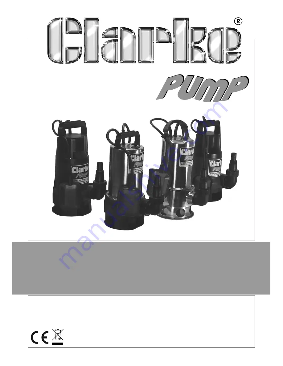
SUBMERSIBLE PUMPS
MODEL NO: PSV3A, PSV4A, PSSV2A &
PVP11A
PART NO: 7236042, 7236044, 7236050 & 7236060
Page 1: ...OPERATION MAINTENANCE INSTRUCTIONS GC04 17 SUBMERSIBLE PUMPS MODEL NO PSV3A PSV4A PSSV2A PVP11A PART NO 7236042 7236044 7236050 7236060...
Page 2: ...d if the product is found to have been abused or tampered with in any way or not used for the purpose for which it was intended Faulty goods should be returned to their place of purchase no product ca...
Page 3: ...cal wiring or equipment 4 Always store the pump out of reach of children and do not allow persons unfamiliar with these instructions to operate it 5 Never direct the discharge flow towards another per...
Page 4: ...there is a person or animal still in the pool 11 Never install the pump on sand silt or mud which is likely to shift or collapse 12 Never modify this pump in any way Use it only for the purpose for w...
Page 5: ...ard If the colours of the wires in the power cable of this product do not correspond with the markings on the terminals of your plug proceed as follows The wire which is coloured Blue must be connecte...
Page 6: ...unding water level changes As the water level rises the switch will float and start the pump As the water level falls so will the float switch until it stops the pump Float switches are factory set to...
Page 7: ...E PUMP 1 ALWAYS raise and lower the pump using a rope attached to the lifting handle 2 Place the pump in a vertical position resting on a firm flat surface in the area that you want to drain If there...
Page 8: ...re there is sufficient water for the float switch to rise and activate the pump 2 If required the range of operation of the float switch can be manually adjusted by positioning the float switch cable...
Page 9: ...be cleaned out either by back flushing or by removing the base plate after undoing the retaining screws and cleaning out by hand 3 If the pump has been used for pumping swimming pool water or salty w...
Page 10: ...d in the system 5 Inlet at base of pump is blocked Raise pump and clear openings 6 Vertical pumping distance too high Reduce height or change the pump discharge fitting 7 Impeller may be damaged Consu...
Page 11: ...cut in 3 A foreign object has jammed the impeller Feature PSV3A PSV4A PSSV2A PVP11A Outlet Tread Dia 1 BSP 1 BSP 1 BSP 1 BSP Outlet Size 38mm 38mm 38mm 34mm Voltage 230 Vac 230 Vac 230 Vac 230 Vac Mo...
Page 12: ...Cable Sheath 4 Top Housing 23 O Ring 5 Cable Entry Sheath 24 Adjusting Shim Washer 6 Cable Entry Gland 25 Impeller 7 Capacitor 8uF 26 Nut 8 Cable Gland 27 Main Pump Housing 9 Cable Holder 28 Steel Bal...
Page 13: ...13 Parts Service 020 8988 7400 E mail Parts clarkeinternational com or Service clarkeinternational com PARTS DIAGRAM PSV3A PSV4A...
Page 14: ...Body 31 Compression Ring 8 O ring 32 Bolt 9 Pump Rear Housing 33 Ground Bracket 10 Cable Entry Sheath 34 Locating Ring 11 Cable Sheath 35 Sealing Washer 12 Cable Gland 36 Base Cover Ring 13 Capacitor...
Page 15: ...15 Parts Service 020 8988 7400 E mail Parts clarkeinternational com or Service clarkeinternational com PARTS DIAGRAM PSSV2A...
Page 16: ...29 Front Motor Cover 7 Main Pump Body 30 Mechanical Seal 8 O Ring 31 Adjusting Shim Washer 9 Pump Rear Housing 32 Shim Washer 10 Cable Entry Sheath 33 Impeller 11 Cable Gland 34 Nut 12 Capacitor 8uF 3...
Page 17: ...17 Parts Service 020 8988 7400 E mail Parts clarkeinternational com or Service clarkeinternational com PARTS DIAGRAM PVP11A...
Page 18: ...18 Parts Service 020 8988 7400 E mail Parts clarkeinternational com or Service clarkeinternational com PUMP PERFORMANCE GRAPHS...
Page 19: ...19 Parts Service 020 8988 7400 E mail Parts clarkeinternational com or Service clarkeinternational com DECLARATION OF CONFORMITY...
Page 20: ......