background image

17

Parts & Service: 020 8988 7400 / E-mail: [email protected] or [email protected]

• A dull chisel can be detected by the amount of excess force 

required to complete a cut.

• After the first cut, the workpiece must be moved along in the correct 

direction relative to the slot in the chisel, to allow chips to clear 
freely. Move the workpiece so that the chisel slot is releasing chips 
into the already cut part of the mortice.

• Do not have the slot against the blind end of the mortice, as the 

chips will not be able to clear from the chisel. This will cause 
overheating and possible breakage to the chisel or bit.

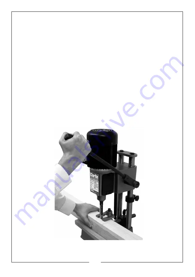
• When cutting deep mortises, make the cut in several stages of 

approximately 25mm each, to allow chips to clear.

• When performing a through mortice, a piece of wood should be 

placed between the workpiece and the table. This prevents the 
wood from splintering when breaking through the bottom of the 
mortise  and also prevents damage to the table.

• Always switch the morticing machine off after use. Never leave the 

machine running unattended.

Summary of Contents for 6500015

Page 1: ...OPERATING MAINTENANCE INSTRUCTIONS ORIGINAL INSTRUCTIONS GC0321 REV 4 MORTICING MACHINE MODEL NO CBM1 B PART NO 6500015 ...

Page 2: ...y way or not used for the purpose for which it was intended Faulty goods should be returned to their place of purchase no product can be returned to us without prior permission This guarantee does not effect your statutory rights ENVIRONMENTAL RECYCLING POLICY Through purchase of this product the customer is taking on the obligation to deal with the WEEE in accordance with the WEEE regulations in ...

Page 3: ...y time without prior notice ACCESSORIES The following Morticing Chisels and Bits are available from your CLARKE dealer Mortice Width Bit Shank Size Part No 1 6mm 1 4 5mm 6500025 2 9mm 3 8 6mm 6500026 3 13mm 1 2 9mm 6500027 4 16mm 5 8 13mm 6500028 Model Number CBM1B Dimensions L x W x H 338 x 342 x 290 mm Weight 27 5 kg Power Supply 230V 50Hz 1ph Power rating 370 Watts i 2HP Speed 1500 rpm Hold Dow...

Page 4: ...l reduce risk of electric shock 2 Avoid body contact with earthed or grounded surfaces such as pipes radiators ranges and refrigerators There is an increased risk of electric shock if your body is earthed or grounded 3 Do not expose power tools to rain or wet conditions Water entering a power tool will increase the risk of electric shock 4 Do not abuse the cable Do not use the cable for carrying p...

Page 5: ...eep your hair and clothing away from moving parts Loose clothes jewelry or long hair can be caught in moving parts 7 If devices are provided for the connection of dust extraction and collection facilities ensure these are connected and correctly used Use of dust collection can reduce dust related hazards POWER TOOL USE AND CARE 1 Do not force the power tool Use the correct power tool for your appl...

Page 6: ...ne on before clearing the table of all objects tools scrap pieces etc 5 Always keep hands fingers and hair well away from the rotating bit 6 Do not attempt to mortice materials that do not have a flat surface unless a suitable support is used 7 Always use the Hold Down to prevent work from lifting when withdrawing the chisel 8 Always support the workpiece securely against fence to prevent rotation...

Page 7: ...mains socket could cause an electrical hazard If the colours of the wires in the power cable of this product do not correspond with the markings on the terminals of your plug proceed as follows The Blue wire must be connected to the terminal marked N or coloured Black The Brown wire must be connected to the terminal marked L or coloured Red The Yellow and Green wire must be connected to the termin...

Page 8: ...e your dealer immediately if any parts are missing The essential components are as follows NO DESCRIPTION NO DESCRIPTION 1 Table 9 3 x Hex Keys 4 5 6mm 2 Countersunk Table Screws 10 Dog Clutch 3 Fence 11 Spring 4 Hold Down Post 12 Securing Pin 5 Hold Down 13 Raise Lower Lever 6 Locking Levers 14 Gas Spring Assembly 7 Chuck Key 15 Tool Rack 8 Chisel Drill Bit ...

Page 9: ...dog clutch 3 Thread on to the end of the lever a flat washer followed by the spring a second flat washer and finally the nut 4 Tighten the nut fully 5 The handle is used to raise and lower the head It may be repositioned for maximum leverage and comfort during operation 6 To do this pull the lever away from theshaft as shown and turn it to a more comfortable or appropriate position Release the lev...

Page 10: ... 7 Raise the head using the operating handle to the top of its travel and hold in place by securing the depth stop 8 Attach the damper to its two fittings by pushing it on the spherical housings until they click into place 9 Assemble the table to the base using the two countersunk headed screws provided ...

Page 11: ...he handle outwards against spring pressure then turn the handle to a more convenient position Release the handle to lock it in place and proceed to turn the complete assembly once again Repeat the process as necessary until the lever assembly locks the device in place 13 Finally attach the tool holder to the machine as shown Two hex socket head screws are provided for this purpose INSTALLATION IMP...

Page 12: ...nd bit up through the hole in the head 3 Push the chisel up as far as possible into the head and nip up the grub screw to temporarily hold it in this position using the hex wrench provided 4 You can lower the drill bit gently and allow it to rest on the table whilst carrying out this operation NOTE The opening in the side of the chisel should always be to the right or left never to the front or re...

Page 13: ... CHISEL and NOT the chuck before setting the 1 16 2mm clearance IIf the bit does bottom out in the chuck first slacken off the grub screw securing the chisel and lower it approx 1 16 2mm and try again Alternatively grind off a portion of the drill shank This adjustment is IMPORTANT to ensure a proper clearance is provided between the cutting tips of the bit and the points of the chisel For certain...

Page 14: ...NG CHISEL PARALLEL TO WORKPIECE It is important that the chisel is square to the workpiece To achieve this slacken the chisel securing screw and rotating the chisel until the back surface is flat against the workpiece or a piece of wood with parallel sides resting against the fence then retighten the screw ensuring a distance of at least 1 16 2mm is maintained between the chisel and the end of the...

Page 15: ...ng moved but will not drop under its own weight then raise the stop so that it contacts the underside of the head Lower the head to the maximum depth desired then tighten the stop securing knob ADJUSTING THE HOLD DOWN The purpose of the Hold Down in to prevent the workpiece from lifting as the chisel is raised up out of the hole The hold down should be adjusted so it just touches the top of the wo...

Page 16: ...tton or the RED cover to switch the machine OFF NOTE The switch is a No Volt Release type If the supply is interrupted the ON OFF switch will automatically revert to the OFF position This is a safety device to prevent the machine from starting again should the supply be restored 3 With the machine running feed the chisel and bit steadily into the workpiece by pulling down on the operating handle N...

Page 17: ... the mortice Do not have the slot against the blind end of the mortice as the chips will not be able to clear from the chisel This will cause overheating and possible breakage to the chisel or bit When cutting deep mortises make the cut in several stages of approximately 25mm each to allow chips to clear When performing a through mortice a piece of wood should be placed between the workpiece and t...

Page 18: ...ing of the chisel and bit Sharpen the bit by using a small smooth file following the original shape of the bit File the inside edge of the spur the sides of the brad point and the cutting edge inwards towards the flutes of the bit to restore sharpness Do not file the outside edge of the spur as this will affect the diameter of the bit Use a mortice chisel cutter with the correct size pilot to shar...

Page 19: ...mn 8 Screw 38 Guide Column 10 Screw 39 Depth Set Guide 11 Lock Handle 40 Lock Handle 12 Knob 41 Wood Table 13 Hold down Clamp 42 Screw 14 Guide Column 43 Chisel 15 Screw 44 Chisel Bushing 16 Cover 45 Chuck 17 Nut 46 Screw 18 Washer 47 Screw 19 Spring 48 Gear Shaft 20 Washer 49 Gear Casing 21 Tool Rack 50 Screw 22 Screw 52 Cover 23 Power Cable 53 Switch Box 24 Handle Grips 54 Screw 25 Motor 55 Swit...

Page 20: ...20 Parts Service 020 8988 7400 E mail Parts clarkeinternational com or Service clarkeinternational com COMPONENT PARTS ...

Page 21: ...21 Parts Service 020 8988 7400 E mail Parts clarkeinternational com or Service clarkeinternational com DECLARATION OF CONFORMITY ...

Page 22: ...22 Parts Service 020 8988 7400 E mail Parts clarkeinternational com or Service clarkeinternational com DECLARATION OF CONFORMITY ...

Page 23: ..._ ____________________________________________________________________________ _____________________________________________________________________________ _____________________________________________________________________________ ____________________________________________________________________________ _____________________________________________________________________________ __________...

Page 24: ......

Reviews: