Clarke 230TE Operating & Maintenance Manual Download Page 17

18

WELDING PITFALLS

The arc welding technique is an acquired skill and requires considerable practice
before perfect results are obtained. The diagrams below will help to explain the
pitfalls in your technique and how to overcome them.
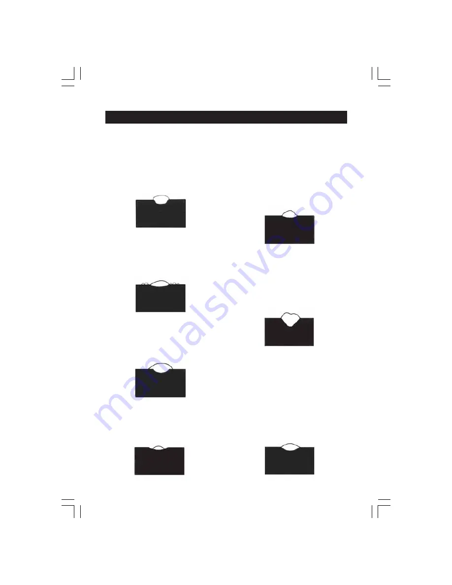
1. Arc too short

This causes irregular masses of weld to
be deposited, with slag contamination
on an uneven surface.

2. Arc too long

This causes poor penetration resulting in
a weak weld with excessive spatter and
porosity. Surface of the weld is rough
and the arc makes a hissing sound

3. Electrode moved too slowly

This causes a very wide and heavy
deposit which overlaps at the sides. It is
wasteful both in terms of time and
electrode use.

4. Electrode moved too quickly

T

his causes poor penetration with a

‘stringy’ and incomplete weld deposit. Slag
is very hard to remove.

5. Current too low

This causes poor penetration and
causes the electrode to stick to the
workpiece too readily. Also results in a
very irregular and high weld deposit.
Slag is very hard to remove.

6. Current too high

This causes excessive penetration with
spatter and deep pointed crater. It may
also cause holes to be burned in the
workpiece.

Burns electrodes very quickly.

7. The perfect weld

With the correct combination of arc
length, current regulation, inclination
and speed of the electrode, you will,
with practice produce the per fect
weld.

This should be regular with uniform
ripples and no slag contamination.

The arc will make a steady, even
crackling sound.

Summary of Contents for 230TE

Page 1: ...OPERATING MAINTENANCE INSTRUCTIONS ARC WELDERS 0807 ARC WELDERS ...

Page 2: ...e product is found to have been abused or tampered with in any way or not used for the purpose for which it was intended Faulty goods should be returned to their place of purchase no product can be returned to us without prior permission This guarantee does not effect your statutory rights CONTENTS 3 PAGE EMC Regulations 4 Safety General 6 Safety Arc Welding 8 Preparation of Working Area 11 Additi...

Page 3: ...AREA Before installing welding equipment the user shall make an assessment of potential electromagnetic problems in the surrounding area Avoid using your inverter in the vicinity of a other supply cables control cables signalling and telephone cables above below and adjacent to the welding equipment b radio and television transmitters and receivers c computer and other control equipment d safety c...

Page 4: ...level 2 4 Equipotential bonding Bonding of all metallic components in the welding installation and adjacent to it should be considered However metallic components bonded to the work piece will increase the risk that the operator could receive a shock by touching these metallic components and the electrodes at the same time The operator should be insulated from all such bonded metallic components 2...

Page 5: ...e A hard hat should be worn when others work overhead Flammable hair preparations should not be used by persons intending to weld or cut B Toxic fume prevention Severe discomfort illness or death can result from fumes vapours heat or oxygen enrichment or depletion that welding or cutting may produce Prevent them with adequate ventilation NEVER ventilate with oxygen Lead cadmium zinc mercury and be...

Page 6: ... suitable fire extinguishing equipment during and for some time after welding or cutting if a appreciable combustibles including building construction are within 10m b appreciable combustibles are further than 10m but can be ignited by sparks c openings concealed or visible in floors or walls within 10m can expose combustibles to sparks d combustibles adjacent to walls ceilings roofs or metal part...

Page 7: ...arks 2 Eye and head protection Protect eyes from exposure to arc NEVER look at an electric arc without protection Welding helmet or shield containing a filter plate shade no 12 or denser must be used when welding Place over face before striking arc Protect filter plate with a clear cover plate Cracked or broken helmet or shield should NOT be worn radiation can pass through to cause burns Cracked b...

Page 8: ...c welding gouging or spot welding operations 2F TO PROTECT AGAINST SHOCK Keep body and clothing dry Never work in damp area without adequate insulation against electrical shock Stay on a dry duckboard or rubber mat when dampness or sweat can not be avoided Sweat sea water or moisture between body and an electrically LIVE part or earthed metal reduces the body surface electrical resistance enabling...

Page 9: ...n so equipped the electrode wire becomes electrically LIVE when the power source switch is ON and welding gun switch is closed Never touch the electrode wire or any conducting object in contact with the electrode circuit unless the welding power source is off b Equipment without output on off control no contactor Welding power sources used with shielded metal arc welding and similar processes may ...

Page 10: ...ied technician If you have a problem with the machine contact your local CLARKE dealer NEVER use or store in a wet damp environment DO NOT EXPOSE TO RAIN NEVER allow children or animals in the vicinity of a welding operation ALWAYS remove all flammable materials from the welding area ALWAYS ensure that there is full free air circulating around the outer casing of the machine and that the louvres a...

Page 11: ...ned from your local dealer or most electrical stockists Fuse Rating The fuse in the plug must be replaced with one of the same rating 13 amps and this replacement must be ASTA approved to BS1362 B ALL OTHER MODELS 230V Supply Connect the mains lead to a suitably fused 230 Volt 50Hz electrical supply The fuse rating should correspond to that shown on the data plate on the rear panel of the machine ...

Page 12: ...lacken the knobs grub screw and remove the knob to reveal a circular plate 2 Remove the two screws securing the plate then reverse the plate 3 Replace the two plate securing screws followed by the selector knob This knob can now be moved to either the 230 or 110 400V position depending upon the position of the plate On later models the position of the screw arrowed in the illustration opposite wil...

Page 13: ...ce with the instructions given under Electrical Connections attach the leads to the machine as shown in Fig 1 on page 14 Ensure the EARTH lead is connected to the WORKPIECE and the other lead to the ELECTRODE HOLDER IMPORTANT Ensure also that the earth clamp is attached to clean solid metal If necessary thoroughly clean with a wire brush or similar to guarantee a good connection 2 Select the appro...

Page 14: ...al J Thermal Current Indicator K Thermal Overload Indicator L Input Voltage Selector Work Clamp Symbol Earth Identifies work terminal Black Knob Electrode Holder Symbol Identifies electrode terminal Red Knob 15 This is an illustration of a typical layout Although with some models the major components may differ slightly in design and location Fig 1 ...

Page 15: ...ed Enter the threaded end of the handle through the holes provided Thread on the plastic nut and tighten Fig 2 It is important to pay attention to the notes on welding shield maintenance given on page 19 When replacing the glass panels use ONLY those parts supplied by Clarke International The dark panel is a certified specific optical class and should not be exchanged for any other type The clear ...

Page 16: ...oise should be heard which is an indication of a good weld NOTE This is the most difficult aspect for most beginners It is recommended that you practice on some scrap material in order to get a feel of the operation If the electrode is not withdrawn quickly enough once the arc is primed there is a possibility that the electrode will weld itself to the workpiece Should this happen give it a sharp t...

Page 17: ...teful both in terms of time and electrode use 4 Electrode moved too quickly This causes poor penetration with a stringy andincompletewelddeposit Slag is very hard to remove 5 Current too low This causes poor penetration and causes the electrode to stick to the workpiece too readily Also results in a very irregular and high weld deposit Slag is very hard to remove 6 Current too high This causes exc...

Page 18: ... cracked have it replaced immediately Replacement clear and dark lenses are available from your Clarke dealer see Parts Lists for details NEVER use any dark filter lens other than that provided by CLARKEInternational oronewiththesamecertified Opticalclass degreeofprotection Theshieldshouldalwaysbecleanedwithacleansoftclothafteruse ensuringthelenses are clean Remove any dust that may have accumulat...

Page 19: ...20 ...

Page 20: ...age of time the machine may be used in a given period for a specified welding current i e using the example above using 2 5mm dia rods 34 may be burned continuously at 80 A welding current or using 4 0mmdiarods 8 5maybeburnedcontinuouslyata160Aweldingcurrent nh indicates the max no of electrodes that may be burned once the overload has operated but has cooled sufficiently for it to begin operating...

Page 21: ...value and dimension of the max supply current I max_ _A Size of the necessary main fuse A _ _ Rated value of the supply voltage U1 V _ _ _ Symbol and dimension for the welding current I2 A Symbol and dimension for the diameter of reference electrodes mm Min and Max rated value of the welding current _ _ _ _ A I2 50Hz Rated frequency for alternating current Min and Max rated no load voltage 1 U 0 _...

Reviews: