CLA-VAL 790-01 Installation Operation & Maintenance Download Page 8

Liner Installation
6", 8", 10", 12" sizes

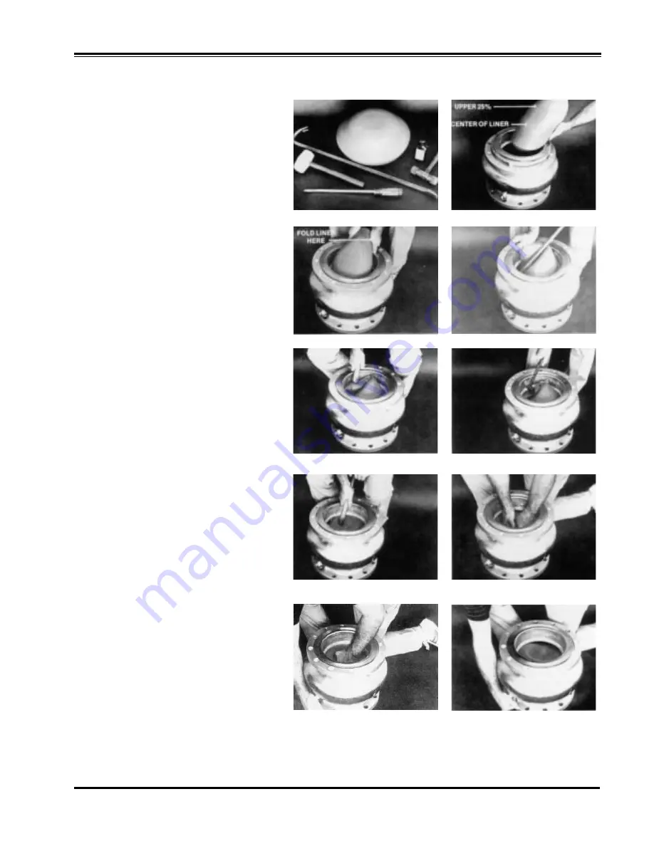
1. Tools required: Bottle of drugstore glycerine, 

30" crowbar, double headed plastic hammer 
with 14" handle, rubber mallet and large flat 
blade screwdriver. 

2. Liberally wipe glycerine on the inside of the 

valve and on the outer edge of the liner. Fold 
liner in half and insert into valve body. 

3. Push liner in as far as possible forcing it out side

ways. 

4. Place the crowbar at the upper 25% point of the 

liner. Take your other hand and push on nose of liner
to bend the liner over the crowbar. The less material
folded over, the easier it will go into the valve. If too
much is folded over, it will be difficult to complete 
liner installation.

5. Continue bending liner nose down into the valve. 

Use your hands and/or hammer handle to continue 
forcing it down into valve. It is important to keep the
"V" of the bend near the 25% point. If it goes over
the center, The liner won't go in, and it will be nec-
essary to start over at Step 3.

6. Use the hammer to force the liner down and out into

the valve body. 

7. Use the hammer handle for the final insertion. 

Sometimes it is helpful to beat on the liner with the 
hammer for the final step. 

8. To seat the liner on the manifold ring use the ham-

mer handle to push down on the liner near bore of 
valve inlet and pry handle and liner towards the cen-
ter. Continue this prying action for 360° around the 
liner for proper seating. 

9. To test for liner seating, push down on the center of

liner and close the loading port shut-off cock, or 
block it with your hand. When you release your hand
from the liner, it should remain in the down position
until the loading port is opened. 

10. If liner appears seated, open loading port cock and 

liner should pop-up to the closed position. Repeat 
Steps 6-10 if liner is not seated. 

When the liner is fully seated, the inside diameter of
the liner will be seated over the outside diameter of
the manifold ring. The manifold ring is a raised circu-
lar ridge at the bottom of the open cavity which pro-
vides for even distribution of the fluid coming in and
going out the loading port. 

Install liner retainer into body.

1

3

5

7

9

2

4

6

8

10

Distributed By: M&M Control Service, Inc.

                http://www.mmcontrol.com/claval-index.php

800-876-0036     847-356-0566

Summary of Contents for 790-01

Page 1: ...Distributed By M M Control Service INC Phone 800 876 0036 Fax 847 356 0747 Email Sales mmcontrol com Distributed By M M Control Service Inc http www mmcontrol com claval index php 800 876 0036 847 35...

Page 2: ...Distributed By M M Control Service Inc http www mmcontrol com claval index php 800 876 0036 847 356 0566...

Page 3: ...Distributed By M M Control Service Inc http www mmcontrol com claval index php 800 876 0036 847 356 0566...

Page 4: ...lower line pressure to a predetermined set point and shall maintain that set point regardless of variations in flow or inlet pressure Control valve shall be constructed of two parts a stainless steel...

Page 5: ...3 Fluid Being Handled 4 Fluid Temperature Range 5 Inlet Pressure Range 6 Outlet Pressure Range 7 Maximum Differential Pressure 8 Minimum Differential Pressure 9 Maximum Flow Rate 10 Pilot Set Point 2...

Page 6: ...e valve is fully opened when loading pressure is sufficiently reduced to allow the liner to roll back completely and expose the full slot area Restoring loading pressure reverses the liner rolling act...

Page 7: ...sed Install the valve between the flanges being sure to include the appropriate flange gas kets between each end of the valve and the mating pipe flange Note The valve must be installed with the flow...

Page 8: ...alve body 7 Use the hammer handle for the final insertion Sometimes it is helpful to beat on the liner with the hammer for the final step 8 To seat the liner on the manifold ring use the ham mer handl...

Page 9: ...COMPOUNDS CAN SEVERELY ATTACK THE LINER MATERIAL 3 Fold the liner as shown and install into the valve body con trol chamber as deeply as possible 4 Continuing to force the liner into the control cham...

Page 10: ...se of the CRD Pressure Reducing Pilot Control to fully relieve all loading on the range spring Slowly open the upstream main line block valve to pressurize the inlet sec tion of the valve Bleed any en...

Page 11: ...ended Pipe layout 6 12 Flange style 100 42 2 Pipe Coupling Rubber Gasket Type 1 100 42 Main Valve Flange X Flange Distributed By M M Control Service Inc http www mmcontrol com claval index php 800 876...

Page 12: ...TM 1 COUPLER FOR GROOVED PIPE 2 SPOOL STRAINER ASSEMBLY WITH CONE 3 100 42 MAIN VALVE GROOVE X FLANGE 4 100 42 MAIN VALVE GROOVE X GROOVE Recommended Pipe layout 6 12 Grooved style 100 42 Distributed...

Page 13: ...Stainless Steel Steel Cad Pl Steel Cad Pl Recommended Spare Part 4 Wafer Style Valve 2 3 Wafer Style Valve 6 12 Flanged Valve 6 5 5 1 2 3 4 5 6 4 3 2 8 7 1 When ordering please specify All nameplate d...

Page 14: ...Distributed By M M Control Service Inc http www mmcontrol com claval index php 800 876 0036 847 356 0566...

Page 15: ...Distributed By M M Control Service Inc http www mmcontrol com claval index php 800 876 0036 847 356 0566...

Page 16: ...assemble and reassemble properly refer to Reassembly Worn disc Disassemble remove and replace disc retainer assembly Yoke dragging on inlet nozzle Disassemble and reassemble properly refer to Reassemb...

Page 17: ...Hex Nut Diaphragm Washer Diaphragm Plug Body Gasket Plug Disc Retainer Assy 15 75 psi Disc Retainer Assy 30 300 psi Disc Retainer Assy 2 6 5 psi Disc Retainer Assy 2 30 psi Yoke Body 1 4 Seat Assy Bu...

Page 18: ...Distributed By M M Control Service Inc http www mmcontrol com claval index php 800 876 0036 847 356 0566...

Page 19: ...screen stock number 68373A All other parts available only in replacement assembly Standard 60 mesh pilot system strainer for fluid service PL X43 R 6 00 PARTS LIST Distributed By M M Control Service I...

Page 20: ...Distributed By M M Control Service Inc http www mmcontrol com claval index php 800 876 0036 847 356 0566...

Page 21: ...Check spring for visible distortion cracks and breaks Inspect all parts for damage corrosion and cleanliness CLEANING After disassembly and inspection cleaning of the parts can begin Water service usu...

Page 22: ...r Stamped on Side Description CV Flow Control Part Description Material ITEM DESCRIPTION QUAN 1 Cap SS only 1 2 Nut Jam 1 3 Seat 1 4 Gasket 1 5 Disc 1 6 Spring 1 7 Ring Retaining 1 8 Stem 1 9 O Ring 1...

Page 23: ...Distributed By M M Control Service Inc http www mmcontrol com claval index php 800 876 0036 847 356 0566...

Page 24: ...end details type of pilot controls used and control adjustment ranges Identification Plate For product identification cast in body markings are supplemented by the identification plate illustrated on...

Page 25: ...001407C R2002101A R2002102J R22002103G R2002104E R2002105A R2002106K R2002107H LINER PART NUMBERS 2 3 4 6 8 10 12 Natural Rubber 65 Durometer EPDM 70 Durometer Nitrile 70 Durometer Silicone 70 Duromet...

Reviews: