CKD ECS2-G4-00-50G-49-L-T2YD-D-H Instruction Manual Download Page 1


INSTRUCTION MANUAL


取扱説明書


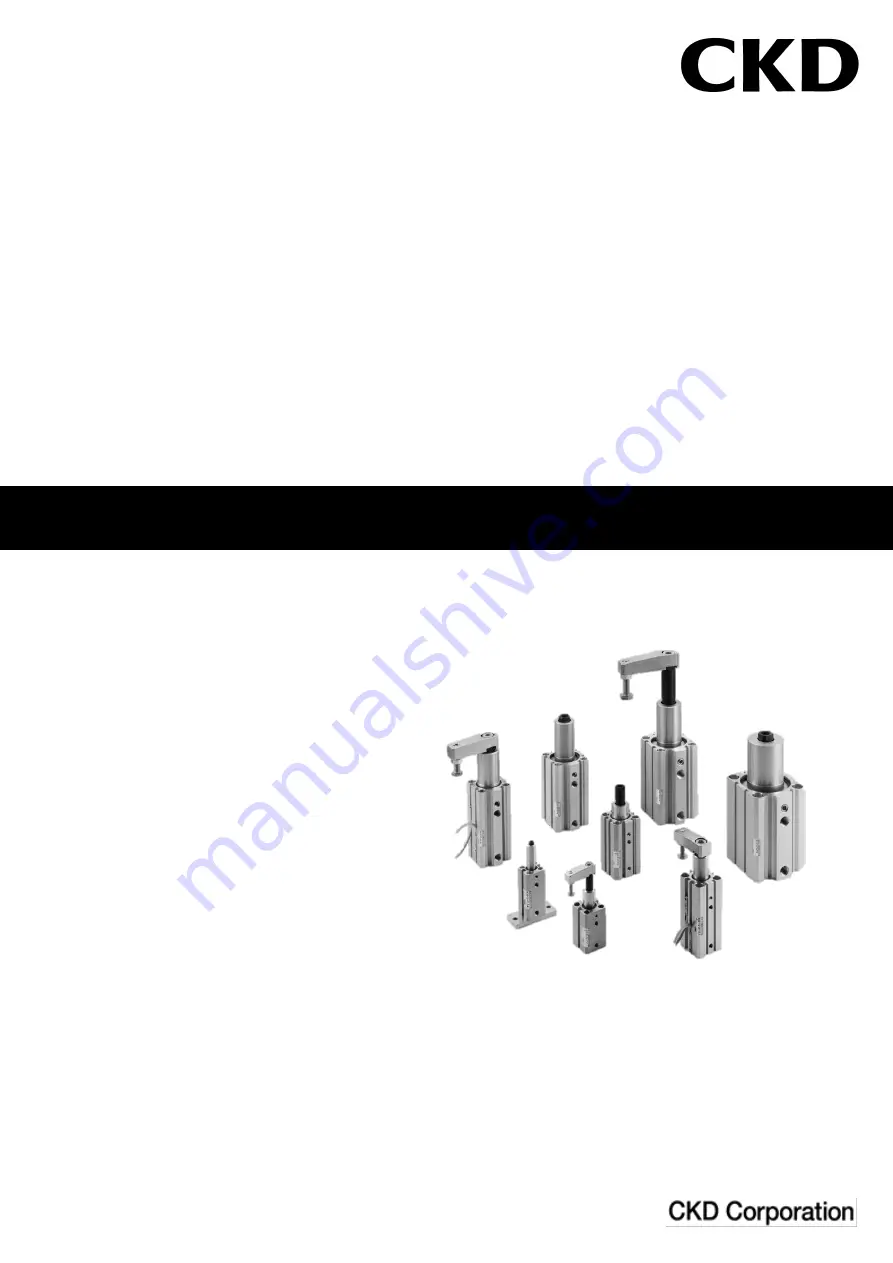
Rotary Clamp Cylinder   

(Single Guide)


RCS2 Series (

φ

12

~φ

63)


SM-T000001-A 


SM-358642 


•  Read this Instruction Manual before using the product. 

•  Read the safety notes carefully. 

•  Keep this Instruction Manual in a safe and convenient place for future reference. 

Summary of Contents for ECS2-G4-00-50G-49-L-T2YD-D-H

Page 1: ...Cylinder Single Guide RCS2 Series 12 63 SM T000001 A SM 358642 Read this Instruction Manual before using the product Read the safety notes carefully Keep this Instruction Manual in a safe and conveni...

Page 2: ...The product is intended for users who have basic knowledge about materials piping electricity and mechanisms of pneumatic components CKD shall not be responsible for accidents caused by persons who s...

Page 3: ...have been adopted in the product customer s improper handling may lead to an accident To avoid this Thoroughly read and understand this Instruction Manual before using the product To explicitly indica...

Page 4: ...2 2 4 1 Piping 12 2 4 2 2 5 Wiring 14 Reed switch 14 2 5 1 Proximity switch T type 16 2 5 2 Proximity switch F type 19 2 5 3 3 USAGE 22 3 1 Using the cylinder 22 3 2 Using the switch 27 4 MAINTENANCE...

Page 5: ...over 50 50 63 63 E Stroke mm F Rotation direction G Switch model No H Switch quantity 12 16 17 5 27 5 37 5 R Rotated 90 in CW Described on page 2 R 1 on rod side 20 25 19 5 29 5 39 5 direction when p...

Page 6: ...ire T3YH T3YV T2YD 2 color display AC magnetic field 2 wire T2YDT T2JH T2JV 1 color display off delay 2 wire F2S Proximity 1 color display 2 wire F3S 3 wire F2H F2V 2 wire F3H F3V 3 wire F3PH F3PV 1 c...

Page 7: ...ide 84 150 201 377 804 1256 1963 3117 mm2 Push side 113 201 314 490 603 1056 1649 2803 1 With constant pressurization RCS2 T2 Packing material fluoro rubber Descriptions RCS2 T2 Bore size mm 12 16 20...

Page 8: ...ezing Port size Rc1 8 NPT1 8 G1 8 Rc1 4 NPT1 4 G1 4 Stoke tolerance mm 1 2 0 Working piston speed mm s 50 200 Cushion Rod side rubber cushioned Head side no cushioning Lubrication Not required use tur...

Page 9: ...protective measures Proximity 2 wire T switch Descriptions Proximity 2 wire T1H T1V T2H T2V T2JH T2JV Off delay T2YH T2YV 2 color display T2WH T2WV 2 color display Applications For programmable contr...

Page 10: ...e No failure after 1 minute of 1 000 VAC applications Ambient temperature 10 14 F to 60 C 140 F Degree of protection IEC standard IP 67 JIS C 0920 water tight oil resistant Proximity 2 wire For AC mag...

Page 11: ...ing ambient temperature around the switch is higher than 25 C 5 mA to 10 mA at 60 C Proximity 3 wire F switch Descriptions Proximity switch F3H F3V F3S F3PH F3PV F3YH F3YV Applications For programmabl...

Page 12: ...e careful with the filtration rate a filter that removes particles exceeding 5 m is desirable flow rate and mounting position install the filter near the directional control valve 2 2 Unpacking Check...

Page 13: ...make sure that the clamp lever attached to the tip of the piston rod does not interfere with external peripheral equipment This cylinder the piston rod strokes while rotating 90 during operation If th...

Page 14: ...on first and the position where it is turned off The middle of the two positions is the highest sensitivity position at that piston position About the mounting surface of the switch There is no restr...

Page 15: ...5 3 9 26 5 13 5 3 9 29 5 16 5 5 5 9 5 Bore size mm Proximity switch T2Y T3Y T1 T2YD T2YDT Reed switch T0 T5 Reed switch T8 RD HD Operating range reference value Hysteretic RD HD Operating range refere...

Page 16: ...predetermined piston speed Install the filter for removing rust foreign matters and drainage from the piping as close as possible to the solenoid valve Observe the effective thread length for the gas...

Page 17: ...r inside of the pipes or device and cause a failure When using a seal tape wind it around the screw threads in the direction opposite from the screw threads and press it down with your fingers to atta...

Page 18: ...light up In that case reversing the polarity of the connection of the lead wires of the switch will light up the indicator Contact protection measures When the switch is used with an inductive load s...

Page 19: ...is the sum of the voltage drop of all switches The indicator will light up only when all the switches turn on Parallel connection There is no limitation on the number of units that can be connected i...

Page 20: ...ire length exceeds 10 m See Ex 3 and 4 2 wire type Ex 5 3 wire type Switch Load Brown Black Blue DC power for switch and load 10 VDC to 28 VDC Example of 3 wire basic circuit 1 When same power is used...

Page 21: ...ack Blue Blue Brown Switch Switch COM 2 wire connection to source input internal power Blue Brown Input termi nals Programmable controller 2 wire connection to source input external power Blue Brown S...

Page 22: ...ally be ignored For the 3 wire type switch the indicator will light up without dimming Switch for alternating magnetic field T2YD When using the switch with a welding current exceeding 14000 A of alte...

Page 23: ...tch is turned on When the lead wire length exceeds 10 m See Ex 8 and 9 2 wire type Ex 10 3 wire type Example of F3 F3Y basic circuit 2 When separate power is used for switch and load DC power for swit...

Page 24: ...lack Blue Blue Brown Switch Switch COM F2 F2Y connection to source input internal power Blue Brown Input termi nals Programmable controller F2 F2Y connection to source input external power Blue Brown...

Page 25: ...a connected load to determine the number of switches to connect For the F2 and F2Y type switch the indicator may become dim or not light up Although the leakage current of a F3 and F3Y type switch in...

Page 26: ...Mount a speed controller to adjust the piston speed Clamp lever allowable moment of inertia and piston speed The upper limit of the clamp lever s allowable moment of inertia differs depending on the p...

Page 27: ...23 Moment of inertia calculation When rotary shaft passes through the workpiece...

Page 28: ...s surroundings This cylinder the piston rod strokes while rotating 90 during operation Usage precautions CAUTION Be sure to observe the following precautions and use Using this product so as to apply...

Page 29: ...25 Do not clamp the product in the rotational direction Do not use as a stopper Do not clamp the inclined portion...

Page 30: ...26 Do not move the workpiece with exterior power Do not install horizontally...

Page 31: ...of bending resistance as robot wires Ambient temperature The switch cannot be used in a high temperature environment 60 C or more Using the switch in a high temperature environment may affect its per...

Page 32: ...m 4 1 1 Piston rod end fittings support metal mounting bolts loosening of nuts Operating condition Change in piston speed and cycle time External leakage internal leakage Scratch and deformation of th...

Page 33: ...Use the snap ring pliers for holes to remove the C ring for 12 16 is R ring For 12 16 40 50 63 remove the C ring on the rod side For 20 25 32 remove the C ring on the head side CAUTION Use snap ring...

Page 34: ...At this time the rod metal assembly and the piston rod assembly disengage at the same time 4 Remove the guide pin inserted in the rod metal Move the piston rod assembly toward the head side insert th...

Page 35: ...es wears cracks on the piston surface Loose connection of piston rod and piston Crack of both end covers Scratches and wear of sliding part packing coil scraper rod packing piston packing wear ring Sc...

Page 36: ...pply the grease to the inner circumferential of the main body from the head side Inserting the rod metal assembly into the main body align the axial direction and rotational direction so that the guid...

Page 37: ...20 RCS2 20K RCS2 T2 20K 2 3 6 9 11 14 16 17 25 RCS2 25K RCS2 T2 25K Guide pin kit Bore size Common to RCS2 standard RCS2 T2 Consumable part number 12 RCS2 G 12 6 7 16 RCS2 G 16 20 RCS2 G 20 7 8 25 RCS...

Page 38: ...6 50 RCS2 50K RCS2 T2 50K 63 RCS2 63K RCS2 T2 63K Guide pin kit Bore size Common to RCS2 standard RCS2 T2 Consumable part number 32 RCS2 G 32 7 8 40 RCS2 G 40 7 8 50 RCS2 G 50 63 RCS2 G 63 For RCS2 T2...

Page 39: ...Consumable part number 32 RCS2 32K 2 5 8 11 12 17 18 19 40 RCS2 40K 2 5 7 10 11 16 17 50 RCS2 50K 63 RCS2 63K Guide pin kit Same as for RCS2 standard Bore size For RCS2 G4 Consumable part number 32 R...

Page 40: ...ondition Change packing Insufficient flow rate Check piping status Check the opening of the speed control valve Cylinder installation is bad Confirm that the cylinder is firmly installed The mounting...

Page 41: ...ed relay or replace switch Cylinder speed is too high for intermediate position detection Lower the speed Switch does not turn off Piston is not moving Move the piston Contact is welded Replace the sw...

Page 42: ...ting it into your company s machinery and equipment have the function structure etc that is provided in the industry s common wisdom In the case where it is caused by unforeseeable reasons in the tech...

Reviews: