Civintec CRYSTAL TOUCH CT5, Installation Manual
Get ready to experience the ultimate security solution with Civintec CRYSTAL TOUCH CT5. Ensure hassle-free installation by downloading the free Installation Manual from our website. The manual provides step-by-step instructions for a seamless setup process. Elevate your security with Civintec CRYSTAL TOUCH CT5. Download the manual from manualshive.com.
Share
Download


Reviews:
No comments
Related manuals for CRYSTAL TOUCH CT5

DUB-1310
Brand: D-Link Pages: 2

CD 300
Brand: Nakamichi Pages: 2
MM300 - 2
Brand: SWEEX Pages: 47
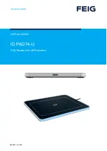
ID PAD74-U
Brand: Feig Electronic Pages: 15
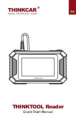
THINKTOOL
Brand: Thinkcar Pages: 5

CDC-X155M
Brand: Aiwa Pages: 5

CDC-X7070MYL
Brand: Aiwa Pages: 36

QUICKSCAN 6000 PLUS
Brand: Datalogic Pages: 104

CP002-EM
Brand: C Prox Pages: 2

VB 4000
Brand: SAL Pages: 60

45-02153-131
Brand: Agri-Fab Pages: 8

NLS-HR15XX-3E
Brand: Newland Pages: 114

C-430
Brand: Sunrich Tech Pages: 4

Prestige Home Theater Sytem
Brand: Audiovox Pages: 4

Encompass 6
Brand: TransCore Pages: 2

ALICANTE CD30
Brand: Blaupunkt Pages: 21

ISO-P32C32
Brand: ICP Pages: 56

RCD 238DAB-BT
Brand: Caliber Pages: 13


