background image

Civemasa Implementos Agrícolas 

27

GDFH

Assembly

Hydraulic circuit assembly

NOTE

NOTE

The cylinder rod must be facing the side of the front stabilizer bar (A).

Couple the hoses on the hydraulic cylinder, with proper tightening and avoiding that 

they touch the soil.

10

10

11

11

07

07

06

06

01

01

A

A

Drawbar circuit

Drawbar circuit

04

04

03

03

02

02

12

12

12

12

10

10

09

09

08

08

04

04

05

05

Wheelset circuit

Wheelset circuit

In order to protect the cylinder terminals, the cylinder is delivered facing 

down. In order to leave it facing up, just turn the cylinder barrel, not being 

necessary to unassemble the set.
Always use thread sealing tape to couple the male quick couplers to the hoses.

Summary of Contents for GDFH

Page 1: ...OPERATOR S MANUAL GDFH GDFH ...

Page 2: ...s The GDFH model also features a central articulation in the frame with ideal buoyancy to follow the surface unevenness or even to perform a finishing job on broad based terraces This operator s manual contains the necessary information for the best performance of this disk harrow The operator must carefullyreadtheentiremanualbeforeworkingwiththeequipment Also read and understand the safety recomm...

Page 3: ... Set up instructions 29 to 33 Preparing the tractor Preparing the disk harrow Hitching to the tractor 29 Procedures to transport the equipment 30 to 33 7 Adjustments and operations 34 to 40 Cutting depth adjustment 34 35 Ways to start the harrowing 36 Direction of the maneuvers 37 Troubleshooting guide 38 39 Operations Important points 40 8 Maintenance 41 to 48 Lubrication 41 Lubrication points 42...

Page 4: ...ncorrect use of the equipment The warranty shall not be applied to any equipment or any part thereof which has been altered elsewhere than at the place of manufacture or which the original purchaser thereof at retail has used or allowed to be used parts not made or supplied by Civemasa NOTE The acquisition of any Civemasa product assures to the original purchaser the following rights Warranty cert...

Page 5: ...occur U U s s o o d d e e E E P P I I O O B B R R I I G G A A T T Ó Ó R R I I O O U s o d e E P I O B R I G A T Ó R I O Products such as oil fuel filters batteries and others must not be spilt over the soil as they can penetrate the underground layers compromising nature Ecological and conscious disposal of them should be done Read and understand the information before making any adjustment or mai...

Page 6: ...ated seeds make any contact with your skin or clothes Keep access and work places clean or free from oil and grease Risk of accidents The presence of any other people on the tractor or equipment is stricly forbidden Have extreme caution when driving under electrical power lines Any contact may result in severe shocks injuries or death For your protection and safety always wear adequate clothes and...

Page 7: ...rrow locations When setting the disk harrow to transport position check if there are no people or animals close or under it In case of emergency know how to stop the tractor and equipment quickly Always shut down the engine remove the key and use the handbrake before leaving the tractor seat Do not drive the equipment under the influence of alcohol or any soothing stimulating medicine as it may re...

Page 8: ...hoist use the appropriate points to lift Underpin the equipment appropriately Use chock blocks and safety chains to secure the equipment to the truck or trailer during the transport After 8 to 10 km transporting please inspect the load condition Repeat this procedure every 80 to 100 km Give more attention when transporting the equipment on rough roads slopes and other adverse conditions Always be ...

Page 9: ... the frame When carrying out any maintenance or when transporting the equipment hitch the cables to all lifting points Use chains of at least 3 meters long to lift the equipment safely Use the adequate points for lifting and be sure that the equipment is safe Avoid accidents Always keep a safe distance from the equipment ...

Page 10: ...ty decals warn about the equipment points that require more attention and they should be kept in good repair If these decals become damaged or illegible replace them Civemasa provides decals upon request and indication of the respective serial number Safety decals ...

Page 11: ...Civemasa Implementos Agrícolas 10 GDFH Decal set Model Serial number GDFH decal 05 03 03 4707 Civemasa logotype decal 05 03 03 5341 To the operator Safety decals ...

Page 12: ...84 Disc blade type Front gang notched Rear gang plain Bearings Length 192 5 mm Type Regreasable tapered roller bearings Oil volume on the bearings 110 ml Spacer spools Length 192 5 mm Type Iron cast Axle diameter Ø 38 1 mm 1 1 2 Hitching type Drawbar Tires 11L15 10 ply 600 x 16 6 ply 7 50 x 16 10 ply Working speed 7 to 12 Km h Model Number of disc blades Cutting width mm Weight Kg Tractor required...

Page 13: ... 1100 2400 52 6065 1200 2555 5125 1100 2400 56 6465 1200 2555 5525 1100 2400 60 6860 1200 2555 5920 1100 2400 64 7230 1200 2555 6290 1100 2400 68 7620 1200 2555 6680 1100 2400 72 8040 1200 2555 7100 1100 2400 76 8440 1200 2555 7500 1100 2400 80 8840 1200 2555 7900 1100 2400 84 9225 1200 2555 8285 1100 2400 Measures in millimeters NOTE F F D D E E C C B B A A ...

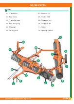
Page 14: ...7 7 8 8 9 9 9 9 9 9 9 9 11 11 5 5 5 5 1 1 3 3 2 2 4 4 6 6 10 10 12 12 01 Front frame 07 Drawbar set 02 Rear frame 08 Tractor hitch 03 Front disc gang 09 Transport lock 04 Rear disc gang 10 Transport bar 05 Wheelset 11 Hoses 06 Parking jack 12 Opening system ...

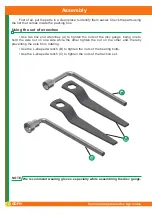
Page 15: ...Use two box end wrenches A to tighten the nuts of the disc gangs being one to hold the axle nut on one side while the other tighten the nut on the other end thereby preventing the axle from rotating Use the L shaped wrench B to tighten the nuts of the bearing bolts Use the L shaped wrench C to tighten the nuts of the traction set We recommend wearing gloves especially while assembling the disc gan...

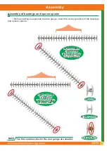
Page 16: ...er spools The first and last disc on the rear gangs are smaller NOTE 46 disc blades 46 disc blades 12 bearings 12 bearings 32 spacer spools 32 spacer spools 2 furrow fillers 2 furrow fillers 50 disc blades 50 disc blades 12 bearings 12 bearings 36 spacer spools 36 spacer spools 2 furrow fillers 2 furrow fillers Bearing Bearing Spacer spool Spacer spool Furrow filler Furrow filler ...

Page 17: ...Furrow filler Furrow filler 54 disc blades 54 disc blades 12 bearings 12 bearings 40 spacer spools 40 spacer spools 2 furrow fillers 2 furrow fillers 58 disc blades 58 disc blades 12 bearings 12 bearings 44 spacer spools 44 spacer spools 2 furrow fillers 2 furrow fillers The first and last disc on the rear gangs are smaller NOTE ...

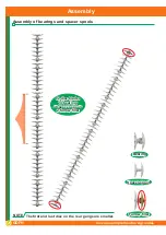
Page 18: ...Furrow filler Furrow filler 62 disc blades 62 disc blades 16 bearings 16 bearings 40 spacer spools 40 spacer spools 2 furrow fillers 2 furrow fillers 66 disc blades 66 disc blades 16 bearings 16 bearings 44 spacer spools 44 spacer spools 2 furrow fillers 2 furrow fillers The first and last disc on the rear gangs are smaller NOTE ...

Page 19: ...16 bearings 48 spacer spools 48 spacer spools 2 furrow fillers 2 furrow fillers 74 disc blades 74 disc blades 20 bearings 20 bearings 48 spacer spools 48 spacer spools 2 furrow fillers 2 furrow fillers Bearing Bearing Spacer spool Spacer spool Furrow filler Furrow filler The first and last disc on the rear gangs are smaller NOTE ...

Page 20: ...s and spacer spools 78 disc blades 78 disc blades 20 bearings 20 bearings 52 spacer spools 52 spacer spools 2 furrow filler 2 furrow filler Bearing Bearing Spacer spool Spacer spool Furrow filler Furrow filler The first and last disc on the rear gangs are smaller NOTE ...

Page 21: ...s and spacer spools 82 disc blades 82 disc blades 24 bearings 24 bearings 48 spacer spools 48 spacer spools 2 furrow filler 2 furrow filler Bearing Bearing Spacer spool Spacer spool Furrow filler Furrow filler The first and last disc on the rear gangs are smaller NOTE ...

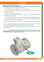
Page 22: ...and a nut C 1 Place the bolt H that fasten the lock nut I along with a spring washer and nut only on the outer side of the gangs Use the wrenches from the set of wrenches page to tighten the gangs as follows 1 Place one of the wrenches in the outer side of the gangs locked side supporting it on the ground As shown on the next page 2 On the inner side use the other wrench and tighten the gangs to g...

Page 23: ...hreads B must be cleaned and greased before their assembly Consult the torque table NOTE Axle torque Axle diameter Ft lbs 1 1 2 2670 1 5 8 2890 2 1 8 3300 2 1 2 3500 Disc gangs assembly sequence G G C1 C1 I1 I1 H1 H1 B B D D D D E E E E F F F F A A C C H H I I ...

Page 24: ...ront gang turns dirt to the right Assembly In the gang assembly to the carriers the bearing hangers should remain facing the disc blades concavity Put the bolt A and a square washer B passing through the bearing housing and the bearing hanger holes On top put the flat washer and nut Repeat this operation for other bearings A A B B ...

Page 25: ...s A using bolts B and flat washers which are placed underneath the fixation plates On top place a spring washer and nut The scrapers feature an adjustment to approach or distance them from the disc blades on a range from 5 to 10 mm NOTE Frames junction Approach both frames A and B and place the junction pin C along with a flat washer castle nut and cotter pin A A B B C C B B A A ...

Page 26: ...in F flat washer and cotter pin Couple the cylinder rod to the bar A using a bolt G spring washer and nut Assemble the hoses support H to the drawbar using a spring washer and nut Assemble the cylinder D hoses and pass them through the support Check if the terminals are cleaned and avoid that them touch the soil The cylinder terminals must remain facing up Always use thread sealing tape to couple ...

Page 27: ... frame B using bolts C washers and nuts The bolt head must be on the inner side of the hitch bar Then assemble the drawbar D to the hitch bar A using bolts E spring washers and nuts Assemble the hose support F to the drawbar D and to the transport bar G using flat washer and nut Couple the parking jack H to the drawbar using pin and cotter pin D D E E A A H H B B G G F F F F C C ...

Page 28: ...they touch the soil 10 10 11 11 07 07 06 06 01 01 A A Drawbar circuit Drawbar circuit 04 04 03 03 02 02 12 12 12 12 10 10 09 09 08 08 04 04 05 05 Wheelset circuit Wheelset circuit In order to protect the cylinder terminals the cylinder is delivered facing down In order to leave it facing up just turn the cylinder barrel not being necessary to unassemble the set Always use thread sealing tape to co...

Page 29: ... hose 02 05 3 8 X 6120 TR TM hose 02 3 8 X 6500 TR TM hose 02 3 8 X 6700 TR TM hose 02 3 8 X 6900 TR TM hose 02 3 8 X 7100 TR TM hose 02 3 8 X 7300 TR TM hose 02 3 8 X 7500 TR TM hose 02 3 8 X 7700 TR TM hose 02 3 8 X 7900 TR TM hose 02 3 8 X 8100 TR TM hose 02 06 Purple Blue grip coupler 01 01 01 01 01 01 01 01 01 01 07 Purple Red grip coupler 01 01 01 01 01 01 01 01 01 01 08 Black Blue grip coup...

Page 30: ...s when working loose Check the tires inflation and keep the same pressure on both of them Lubricate all grease fittings appropriately See instructions on the lubrication section Hitch the drawbar A to the tractor drawbar using an axle B and cotter pin Note that the drawbar is centralized on the tractor After coupling the hitch pin place the safety chain C ATTENTION NOTE A A C C D D D D B B WRONG W...

Page 31: ... Procedures to transport the equipment A A B B C C E E D D Place the articulation lock B Articulate the transport bar C by removing the pin D and cotter pin lock the pin E and cotter pin on the hole Return the pin D to its original position ATTENTION Never loosen up or remove the hoses without relieving the control valve pressure first ...

Page 32: ... I I H H G G F F Articulate the hitch bar E and lock it to the frame using a pin G and lock pin Assemble the hitch bar H to the lower support of the tractor third point Couple the hoist I to the hitch bar H using a pin and cotter pin Lock the hoist I to the upper support of the tractor third point ...

Page 33: ...ve the pin K on the hole L in a way that the wheelset unlocks and thus can be lowered Activate the hydraulic cylinder M until the wheelset J lowers totally then place the pin K and cotter pin on the hole N Place the transport lock O on the cylinder rod To return to working position repeat the same procedures in reverse way K K L L N N L L N N K K M M O O J J Working position Working position Trans...

Page 34: ...structions Procedures to transport the equipment Use the hoist I with the aid of the safety chain Q that is used to lift the drawbar F NOTE Couple the hitch bar H to the bar C using a hitch pin P which is found with the drawbar F I I Q Q H H C C P P ...

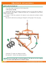
Page 35: ...s In light and loose soils it is appropriate to work with a smaller opening angle To open or close the equipment the operator must activate the hydraulic cylinder control valve Note that the disk harrow opening just change the cutting angle of the rear gang Increasing A bigger disc blades penetration Decreasing A smaller disc blades penetration A A B B NOTE Use the rod stops B to limit the opening...

Page 36: ...irst hole A to get the smallest disc blades penetration angle Displace the bar to the other holes in order to increase the penetration angle Note that this adjustment changes the tractor position related to the previous pass NOTE The adjustments previously described determine the cutting depth so it is necessary to keep an agreement between them for a greater performance A A ...

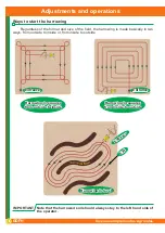
Page 37: ...nside or from inside to outside Note that the harrowed soil should always stay to the left hand side of the operator IMPORTANT Harrowing in squares Harrowing in squares from outside to inside from outside to inside Entrance Entrance Entrance Entrance Harrowing in level Harrowing in level Harrowing in squares Harrowing in squares from inside to outside from inside to outside Exit Exit Entrance Entr...

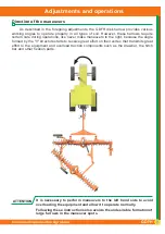
Page 38: ...r make maneuvers to the right because the angle formed by the V structure starts to receive great effort on their vertex that transmits great effort to the equipment and overload traction components such as the drawbar the hitch bar and other fixation parts ATTENTION It is necessary to perform maneuvers to the left hand side to avoid overloading the equipment and allow it to operate normally Follo...

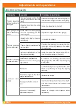
Page 39: ...n a way that the front disc on the left pass on the edge of the furrow Incorrect adjustment of the disc gangs laterally Move the rear disc gang to the left or the front disc gang to the right Windrows forming on the left side Insufficient overlapping Incorrect rear disc gang adjustment If windrows are forming move the front disc gang to the left or the rear disc gang to the right L o c k e d d i s...

Page 40: ...d sealing tape and retighten carefully H y d r a u l i c cylinder leaking Damaged repairings Replace the repairings Damaged rod Replace the rod Oil with impurities Replace the oil repairings and filter elements Working pressure superior than the recommended one Adjust the control valve using the relief valve with the aid of a pressure gauge Normal pressure 180 Kgf cm2 Quick couplers leaking Insuff...

Page 41: ... km h which is not advisable to overcome to maintain service efficiency and avoid possible damages to the equipment Before maneuvering activate the hydraulic cylinder gradually to lift the disc gangs The harrowed ground always stays in the left hand side of the operator Remove pieces of wood or any object that may attach in the disc blades The harrow activation to open or close the disc gangs must...

Page 42: ...roducts contaminated by water dirt or others Remove the remainder old grease around the articulations Clean the grease fittings with a cloth before inserting lubricant and replace the damaged ones Introduce an enough amount of new grease Use medium consistency grease 2 The lubrication of the roller bearings should be done in the same aforementioned period 24 hours 2 1 The roller bearings with oil ...

Page 43: ...Civemasa Implementos Agrícolas 42 GDFH Maintenance Lubricate the points shown above and all grease fittings as well NOTE Lubrication points ...

Page 44: ...nner to avoid that it breaks and to avoid greater maintenance costs since more parts of the set suffer damages when the bearing breaks during the job Check the retainer position A to let the excess of grease flow out of the hub and be careful to not damage the retainer Adjust the castle nut B on the hub using a wrench to get some resistance while turning the hub Do not totally tighten it Lock it u...

Page 45: ...e sure all moving parts have no wear If necessary replace them Replace the missing or damaged safety decals Civemasa can provide these decals under request just being necessary to inform their serial numbers The operator must know the need to keep each decal in good condition and on its proper place The operator also have to know that the lack of safety may be harmful and the higher chance of an a...

Page 46: ...mmended pressure Never weld or heat a wheel The heat can cause increase in pressure with a risk of tire explosion Welding can compromise the structure of the wheel or distort it When filling the tires make sure the hose is long enough for you to stand Also do this process in a safety cage 11L15 tires 10 ply 44 PSI 600 x 16 tires 6 ply 52 PSI 7 50 x 16 tires 10 ply 60 PSI Use Civemasa original part...

Page 47: ...ubber cable Pliers and wrenches Disassembly 1 Remove the end cap A 2 Carefully remove inner assemblies B 3 Disassemble the piston C from the rod assembly by removing lock nut D 4 Slide off gland assembly E and end cap A 5 Remove seals and inspect all parts for damage 6 Install new seals and replace damaged parts with new components 7 Inspect the inside of the cylinder barrel piston rod and other p...

Page 48: ...table on the important data section 3 Lube inside of barrel piston seals and gland seals with hydraulic oil 4 With cylinder body held gently insert the inner assemblies B using a slight rocking motion 5 Apply Loctite 277 before installing the cylinder end cap A 6 Torque cylinder end cap A to 400 lb ft 600 N m Insert the gland E on the cylinder head and align it with the tube so it will fit correct...

Page 49: ...oblems consequently leading to internal leakages lack of power gripping damages to the cylinder rods etc Do not attempt any makeshift repairs to the hydraulic lines fittings or hoses by using tape clamps or cements The hydraulic system operates under extremely high pressure Such repairs will fall suddenly and create a hazardous and unsafe condition Wear proper hand and eye protection when searchin...

Page 50: ...d especially the working speed NOTE To calculate the hourly income of the GDFH disk harrow use the following calculation R L x V x E X Where R Hourly income L Disk harrow working width in meters V Average speed of the tractor in meters per hour E Efficiency 0 90 X Hectare value 10 000 m2 Example using a GDFH disk harrow with 56 disc blades R L 5 26 m V 9 000 m h E 0 90 X 10 000 m2 R 5 26 x 9 000 x...

Page 51: ...8 35 60 5 65 4 58 41 19 64 6 04 4 89 44 03 68 6 43 5 21 46 87 72 6 82 5 52 49 72 76 7 24 5 86 52 78 80 7 62 6 17 55 55 84 8 00 6 48 58 32 To know how many hours will be spent to work a certain previously known area it is necessary to divide the value of the area by the hourly income Example An area of 100 hectares to be worked using a GDFH with 68 disc blades Hourly income 5 21 ha So 100 19 19 5 2...

Page 52: ...Lbs 180 Ft Lbs 3 4 130 Ft Lbs 145 Ft Lbs 200 Ft Lbs 220 Ft Lbs 280 Ft Lbs 315 Ft Lbs 7 8 125 Ft Lbs 140 Ft Lbs 320 Ft Lbs 350 Ft Lbs 450 Ft Lbs 500 Ft Lbs 1 190 Ft Lbs 205 Ft Lbs 480 Ft Lbs 530 Ft Lbs 675 Ft Lbs 750 Ft Lbs 1 1 8 265 Ft Lbs 300 Ft Lbs 600 Ft Lbs 670 Ft Lbs 960 Ft Lbs 1075 Ft Lbs 1 1 4 375 Ft Lbs 415 Ft Lbs 840 Ft Lbs 930 Ft Lbs 1360 Ft Lbs 1500 Ft Lbs 1 3 8 490 Ft Lbs 560 Ft Lbs 11...

Page 53: ...LTDA Marchesan Av 1979 Zip Code 15994 900 MATÃO SP BRAZIL Telephone 55 16 3382 8222 www civemasa com br CIVEMASA reserves the right at any time to make improvements in the design material or specifications of machinery equipment or parts without thereby becoming liable to make similar changes in machinery equipment or parts previously sold Images are for illustration purposes only Some illustratio...

Page 54: ...nte el trabajo 11 No efectuar regulajes con el equipo en funcionamiento 12 No permitir que niños jueguen sobre o próximo de los equipos en operación durante el transporte o almacenado 13 La velocidad de operación debe ser cuidadosamente controlada 14 En terreno inclinado mantenga la estabilidad ideal En inicio de desequilibrio baje la aceleración y no levante el implemento 15 Los implementos de co...

Page 55: ...CIVEMASA IMPLEMENTOS AGRÍCOLAS LTDA CIVEMASA IMPLEMENTOS AGRÍCOLAS LTDA Marchesan Av 1979 Zip Code 15994 900 MATÃO SP BRAZIL Telephone 55 16 3382 8222 www civemasa com br ...

Reviews: