background image

Front Panel 


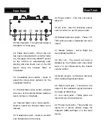
28.


Mic input jack - This jack will accept a 

standard 1/4” male plug. 


29. Fader start switch - When the unit 

has been connected with a control cable 

to a CD player, this is the ON/OFF switch 

for the function to automatically start 

playing and stop (back cue) of the CD 

player using the channel fader or 

crossfader. 


30. Crossfader curve switch - Used to 

select the rising curve patterns for the 

crossfader function. 


31. Channel fader curve control - Adjusts 

the curve of the channel faders between 

quick, normal, or long fade. 


32. Channel fader curve mode switch - 

Used to select the channel fader curve 

desired. 


33. Headphones jack - Used to connect 

your headphones to the mixer. 


Rear Panel


34. Power switch - Turn this unit power 

ON/OFF. 


35. AC inlet - Use the accessory power 

cord to connect to an AC power outlet. 


36. Master balanced output - These 1/4” 

TRS jacks provide a balanced line level 

output. 


37. Master outputs - Left & Right line 

level unbalanced RCA. 


38. Rec out - The record out level is 

dictated by the channel and cross fader 

level, it is not influenced by the master 

volume control. 


39. Send out jack - Connects to the input 

of an outboard signal processor. 


40. Return input jack - Connects to the 

output of the outboard signal processor 

to create an effect loop. 

41. Line input jacks - These jacks are 

inputs for any line level device. 


42. Ph/Aux input jacks - These jacks are 

inputs for a phono (RIAA) stage for 

magnetic (MM) cartridge or a line level 

device. 


28

29

30

31

32

33

29

Summary of Contents for SMFX-200

Page 1: ......

Page 2: ...art is used use caution when moving the cart apparatus combination to avoid injury from tip over 13 Unplug this apparatus during lighting storms or when unused for long periods of time 14 Refer all servicing to qualified service personnel Serving is required when the apparatus has been damaged in any way such as power supply cord or plug is damaged liquid has been spilled or objects have fallen in...

Page 3: ...ent electric shock do not use this polarized plug with an extension cord receptacle or other outlet unless the blades can be fully inserted to prevent blade exposure FEATURES 8 digital effects 3 digital effects for crossfader 3 Kind of channel fader Curve mode Big LCD with Back light Channel and Crossfader Start function Send Return function 3 Band Kill EQ for each channel 2 USB Jacks for PC Playb...

Page 4: ...PART NAMES AND FUNCTIONS 1 2 3 3 3 4 5 5 6 7 8 9 10 11 12 13 14 15 16 17 18 19 23 22 21 20 24 25 26 27 ...

Page 5: ... maximum signal decrease of 12dB Turning the knob in a counterclockwise direction will decrease the amount of treble or bass applied to the microphone signal turning the knob in a clockwise direction will increase the amount of treble or bass applied to microphone signal 6 Channel fader Adjusts the volume for CH1 and CH2 7 Mic ON OFF Talkover switch To set mic on and off when switch at the talkove...

Page 6: ...ap this button to switch TAP BPM function 19 Effect beat selector buttons To select different beat also change the time parameter accoding to the measured BPM of the effector 20 Depth feedback parameter Y Used to adjust the value of the parameter Y mix ratio or resonance or feedback of the effector 21 Time array parameter X Used to adjust the value of the parameter X time of the effector 22 Effect...

Page 7: ...ed to connect your headphones to the mixer Rear Panel 34 Power switch Turn this unit power ON OFF 35 AC inlet Use the accessory power cord to connect to an AC power outlet 36 Master balanced output These 1 4 TRS jacks provide a balanced line level output 37 Master outputs Left Right line level unbalanced RCA 38 Rec out The record out level is dictated by the channel and cross fader level it is not...

Page 8: ... select AUX Always be sure main power is shut off before change the position of the Aux Phone selector switch 44 GND terminals Connect each of your turntable ground leads to either of the two ground terminals 45 USB socket Use the accessory USB cord to connect to a PC 46 Fader start control jacks Connect these jacks to the fader input jacks of the CD player using the 3 5mm stereo mini cord 34 35 3...

Page 9: ...lifier s and or audio receivers such as tape decks Plug your mixer into AC power Now you are ready to switch everything on IMPORTANT Always switch on your audio input sources such as turntables or CD players first then your mixer and finally any amplifiers When turning off always reverse this operation by turning off amplifiers then your mixer and then input devices Turntable Sound system Tape Dec...

Page 10: ...oad 100K ohm Line Aux 25 20KHz 2dB Phono 25 20KHz 2 3dB RIAA Mic 25 20KHz 2 3dB THD N EQ flat maximum gain FX OFF W 20KHz LPF master output load 100K ohm Line Aux Less than 0 04 20 20KHz Phono Less than 0 15 1KHz A weighted Mic Less than 0 15 1KHz A weighted Maximum input 1KHz master output THD 1 EQ flat FX OFF maximum gain Line Aux 4dBV Phono 36dBV Mic 36dBV Return 8dBV Maximum output EQ flat max...

Page 11: ...talkover 14 2dB USB section EQ flat FX OFF W 20KHz LPF master output load 100K ohm Playback Output 0dBV 1V 2dB 20dBfs 1KHz Maximum gain THD N Less than 0 04 0dBfs 1KHz gain at 3 position master 0dBV out Frequency response 31 20KHz 2dB Gain at center S N ratio More than 80dB A weighted gain at center CH separation More than 70dB at 1KHz 0dBfs A weighted gain at center Recording and playback Line 1K...

Reviews: