


ID 19
OPERATION No. ID 100-1 Replacement of engine gearbox
26
TOOLS
16
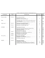
Disconnect the flexible petrol feed pipe from the pump.
17
Disconnect the accelerator control and the choke control from the carburettor . . . . . . . . . . . . . . . . . . . . . . . . .
8 mm box spanner
18
Disconnect the contact breaker feed wires from the coil.
Disconnect the ignition advance control from the distributor.
19
Disconnect the rubber return pipe to the reservoir from the pressure regulator valve .
Disconnect the suspension feed pipe from the pipe union in the distribution box (spanner 2219-T or 2221-T,
see Pl.61, fig.3).
Seal the pipe openings (see Pl.89) . . . . . . . . . . . . . . . . . . . . . . . . . . . . . . . . . . . . . . . . . . . . . . . . . . . . . . . . . . . .
Spanner
2219-T
or
2221-T
20
Disconnect the flexible feed pipe to the heating and demisting radiator from the steel pipe on cylinder head.
21
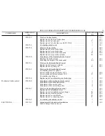
Remove the front suspension spheres (strap wrench 2223-T, see Pl.87, flg.1) and seal the apertures (see Pl.89)
Strap wrench 2223-T
22
Remove the exhaust pipe screen and remove the nuts from the engine fixing studs on the rear brackets
. . . . . .
23 mm spanner
23
Remove the front wheels. Disconnect the flexible couplings (Bibax) from the gearbox driving plates . . . . . . . .
12 mm socket wrench
with extension
24
Remove the fixing screws securing crossmember to sidemembers. Do not mislay either the screws or the
adjusting shims between cross and sidemembers
. . . . . . . . . . . . . . . . . . . . . . . . . . . . . . . . . . . . . . . . . . . .
14 mm box spanner
25
Pass a chain sling (chain sling 1697-T, see P1.42) under the water pump casing. Lift the engine and withdraw
it from the vehicle . . . . . . . . . . . . . . . . . . . . . . . . . . . . . . . . . . . . . . . . . . . . . . . . . . . . . . . . . . . . . . . . . . . . .
Chain sling 1697-T
26
Mount the engine-gearbox assembly on a stand (stand 2497-T, Pl.19)
. . . . . . . . . . . . . . . . . . . . . . . . . . . . . . . .
Stand 2497-T
ASSEMBLY
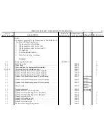
27A
Adjust the rear flexible brackets
(cars delivered before July 1959) (adjusting fixture 1698-T, see Pl.21, 22,23 and 24):
1.
To adjust the lateral position of the brackets:
a) Measure the dimension on the engine-gearbox assembly. Position the gauge as shown on Pl.21
with the point of pin "A" engaged in the crossmember upper fixing hole, unscrew set screw "B"
and slide movable rod "C" so that the pin engages in the hole of plate "D" and in the hole of the
suspension arm. Tighten screw "B"
Summary of Contents for ID 19
Page 1: ......
Page 2: ......
Page 149: ......
Page 174: ......
Page 336: ......
Page 342: ...OPERATION ID 100 3 ENGINE ID 19 2 CROSS SECTION...
Page 357: ......
Page 367: ...OPERATIONS ID 142 4 ENGINE ID 453 6 ACCELERATOR CONTROL 6 ID 19 27 d 6Omm I...
Page 368: ...I 1 2 ENGINE HIOFILTRE AIR FILTER 11 4 9 5 9 7 6 0...
Page 369: ...OPERATION ID 171 3 ENGINE ID 19 VOKES AIR FILTER 29...
Page 371: ...ID 173 3 PETROL PUMP ID 19 INSPECTION FOR LEAKS a b...
Page 375: ...OPERATIONS ID 231 3 ID 231 C ENGINE WATER PUtiF ID 19 35...
Page 380: ...OPERATIONS ID 314 O ID 314 4 CLUTCH CLUTCH CONTROL li i lf ID 19 41 2 5 4 I a...
Page 389: ...OPERATIONS ID 330 2 GEARBOX ID 19 FIRST SPEED SELECTOR LEVER Fig 1 21 98 422 48 Fig 2 98 21...
Page 400: ...OPERATIONS ID 334 o ID 334 1 1 GEARBOX GEAR CHANGE CONTROL ID 19 59 32 T...
Page 403: ...ID 372 l ID 410 3 ID 413 1 8 FRONT AXLE ID 19 SECTIONS 62 23 24 7 OPERATIONS _ 22 i 29...
Page 413: ...OPER ATION3 ID 420 l ID 420 3 REAR AXLE ARM PIVOT BEARING ID19 71 33 34 52 24 23...
Page 425: ...1 5 4 6 Fig 1 Fig 2 _ _ _ __ ID 391 O ID 391 3 SUSPENSION HIGH PRESSURE PUMP ID 19 84 2 3...
Page 426: ...OPERATIONS ID 391 O ID 391 3 SUSPENSION HIGH PRESSURE PUMP Fig 1...
Page 436: ...OPERATIONS ID 443 l ID 443 3 STEERING SECTION OF THE RELAY i ID 19 94 46 53 142...
Page 444: ...OPERATIONS ID 420 3 ID 420 4 ID 451 4 BRAKES ID19 REAR BRAKE BACKPLATE 102 Fig 1 Fig 4 Fig 2 1...
Page 449: ...BRAKES ID 19 107 PEDAL GEAR...
Page 452: ...OPERATIONS ID 454 O ID 454 1 ID 454 4 BRAKES CABLE ADJUSTMENT ID 19 110 I I I I 4 I I I...
Page 455: ...GAUGE RODS sold under No 2307 T ADJUSTMENTS ID 19 PRE ADJUSTMENT 0 F THE FRONT HEIGHT 113 J...
Page 457: ...OpERATlON ID 532 3 ELECTRICAL ID 19 OUCElLlER DYNAMO 7158A 115 29 32 1 1 12 39...
Page 458: ...OPERATION ID 532 3 ELECTRICAL PARIS RHONE DYNAMO GllR91 25 28 30 29 27 19 18 5 11 Pi I 33 c...
Page 459: ...OPERATION ID 532 3 ELECTRICAL ID19 PARIS RHONE DYNAMO GllR91 117 Fig 1 Fig 2...
Page 460: ...OPERATION ID 533 3 ELECTRICAL DUCELLIER STARTER 6003A 6 29 10 4 ID 19 118...
Page 461: ...OPERATION ID 533 3 ELECTRICAL DUCELLIER STARTER 6003A 16 22 21 9...
Page 466: ...ELECTRICAL WIRING DIAGRAM FRONT HARNESS 10 c s t 15 4 47 l I ID 19 123...
Page 467: ...ELECTRICAL WIRING DIAGRAM REAR HARNESS 28 __ P 1 I 6 I ID 19 124 33 c J _ ___ _ J r 4 I 29 30...
Page 468: ...HYDRAULIC ID19 TEST BENCH 125 CONNECTION OF THE IS00 P S I 100 kg cm 2 GAUGE...
Page 469: ...M2 HYORAUL IC ID 19 TEST BENCH 126 CONNECTION OF THE 3000 P S I 200 kg cm2 GAUGE b...
Page 470: ...HYDRAULIC TEST PIPES AND UNIONS ID19 127 K sold under the No 2295 T...
Page 471: ...OPERATION ID 391 O HYDRAULIC HIGH PRESSURE PUMP ID19 128 INSPECTION FOR LEAKAGE S...
Page 473: ...OPERATION ID 393 O HYDRAULIC ID19 PRESSURE DlSTRl6UTlON BLOCK 130 INSPECTION FOR LEAKAGE...
Page 475: ...0DE A T ON IC 391 0 HYDRAULIC MAIN ACCUMULATOR PRESSURE TEST ID 19 132...
Page 481: ......