iDP3240 SERVICE MANUAL
28
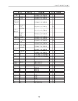
Phenomenon
Recording paper
is not fed. Or
feeding is
disturbed.
Cause
Improper connection of
motor connector.
Improper power supply.
Improper mounting of
control board.
Improper attachment of
platen roller.
Improper attachment
and connection of
thermal head.
Improper feeding of
recording paper.
Foreign matter has
penetrated into the gear
section.
Gear is broken.
Supplied voltage is low.
Motor is defective.
Check Method
Check the state of the
connection of the
connector.
Check if designated AC
adapter is used.
Check the mounting of
the control board and
the condition of its
connections.
Check the attachment of
the platen roller.
Check the mounting and
connection of the
thermal head and the
control board. Check
the wire springs for
deformation or warp.
Check if the recording
paper is jammed, torn or
trapped in the paper
supply path.
Detach the platen roller,
and check if foreign
matter is trapped in the
platen gear or motor
gear.
Detach the platen roller,
or check if the platen
gear or motor gear is
broken.
Check the supplied
voltage using a tester.
Use a tester or an
oscilloscope to measure
voltage.
Repair Method
Connect the connector
correctly.
Use designated AC adapter.
Mount the control board
correctly.
Attach the platen roller
correctly.
Connect the thermal head to
the control board correctly.
Replace a deformed wire
springs.
Remove unnecessary
recording paper and place
paper correctly in the printer.
Remove foreign matter.
Replace broken platen gear. If
the motor gear is broken,
replace the motor.
Operate using a voltage
within the prescribed range.
If the voltage is correct,
replace the motor.
5.2.3 Faulty feeding of recording paper
Summary of Contents for iDP3240
Page 1: ...LINE THERMAL PRINTER MODEL iDP3240 Rev 1 0 First created Feb 10th 2000 Service Manual...
Page 2: ...i REVISION Rev No Date Content Rev 1 0 Feb 10th 2000 First created...
Page 16: ...iDP3240 SERVICE MANUAL 13 3 2 Exploded View 2 5 4 3 71 31 30 29 28 45 44 43 41 52 51 50 49 48...
Page 23: ...iDP3240 SERVICE MANUAL 20 4 3 2 Control PCB Assy Reverse side of the board...
Page 24: ...iDP3240 SERVICE MANUAL 21 4 3 3 Control PCB Assy Top side of the board Parallel Interface...
Page 25: ...iDP3240 SERVICE MANUAL 22 4 3 4 Control PCB Assy Reverse side of the board...
Page 33: ...iDP3240 SERVICE MANUAL 30 6 OUTLINE DRAWING FEED ERROR POWER 9 37 201 119 5 186 123...


