iDP-562 User’s Manual
CITIZEN
14
5.6 DATA Construction
5.6.1 Serial Data format
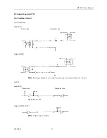
1. Start BIT
2. DATA BIT (+ Parity BIT)
3. Stop BIT (1 ~ 2 BIT)
(1)
START BIT
At 1 / 2 BIT after (a), signal level is checked out, (b). When signal level is SPACE, START BIT is recognized
at this stage. When signal level is MARK, continuous search for START BIT is made for the next bit.
(2)
DATA BIT + PARITY BIT
DATA BIT and PARITY BIT are checked out every 1 / 2 BIT from the half point of START BIT, (b).
Signal level of these points (MARK = 1, SPACE = 0) are read as input DATA.
The sequence of these BIT is BIT 0, BIT 1 ~ PARITY BIT from START BIT.
(3)
STOP BIT
STOP BIT is 1 or 2 BIT and its signal level is MARK. If SPACE LEVEL is read at STOP BIT, FRAMING
ERROR occurs.


