background image

iDP3550/3551 Service Manual

19

CITIZEN

5.2

Disassembly Drawing

Disassembly Drawing-1

Summary of Contents for iDP-3550

Page 1: ...Service Manual DOT MATRIX PRINTER MODEL iDP3550 3551 Rev 3 00 Revised on Jan 25 2002...

Page 2: ...ITIZEN REVISION Rev No Date Comment Rev 1 00 May 10 1999 Newly issued Rev 2 00 Sep 14 2000 Modified the Control Board PF driver IC etc Rev 2 01 Sep 19 2001 Error correction Rev 3 00 Jan 25 2002 Change...

Page 3: ...ous data communication terminals POS terminals kitchen use printers bank card terminals and so on Its abundant built in features allow you to widely use this printer for different applications Prior t...

Page 4: ...y 3550 01 R 3550 02 P 21 5 3 2 Power PCB Assy 3535 03 25 5 4 Parts Layout Drawing 27 5 4 1 Control PCB Assy 3550 01 Serial Interface D sub 25 27 5 4 2 Control PCB Assy 3550 02 Parallel Interface 28 5...

Page 5: ...iDP3550 3551 Service Manual 1 CITIZEN 1 HANDLING AND MAINTENANCE OF PRINTER See the User s Manual coming with the printer body...

Page 6: ...ESC POS mode The user can select themode with the DIP switch and presetjumpers Print function On line self test and hex dump print function Provided by operating the power LF and SEL switches Input b...

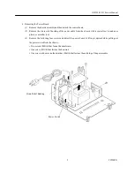
Page 7: ...anual 3 CITIZEN 3 DISASSEMBLY AND REASSEMBLY 3 1 Disassembly Procedure 1 Removing the Top Cabinet 1 Remove the printer cover 2 Remove the four screws M3 12 and detach the top cabinet by gently lifting...

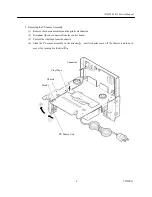
Page 8: ...3 6 from the bottom and gently lift the chassis assembly upward Pull out the power cable from the bottom cabinet 3 Removing the Printer Mechanism 1 Remove the top cabinet 2 Remove the two screws M3 14...

Page 9: ...with a special tool round nose pliers or a similar tool 3 Remove the following four screws and detach the power board by lifting it upward while pulling out the power switch from the chassis Two scre...

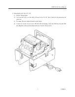
Page 10: ...the printermechanism 2 Disconnect the one connector from the control board 3 Peel off the vinyl tape from the chassis 4 Slide the PE sensor assembly in the direction until its hooks come off the chas...

Page 11: ...tie to set the cable of the auto cutter AC 134 that is fastened to the printer mecha nism free 3 Disconnect the one connector from the control board 4 Loosen not remove the one screw M2 6 6 and disen...

Page 12: ...push the paper cutter toward you to disengage it from the two claws Reassembling the Paper Cutter iDP3550 While facing the cutter blade away from you gently insert the paper cutter into the paper cutt...

Page 13: ...n mount the auto cutter AC 134 are as follows DP 61 DP 62 and DP 65 2 Packing List See Fig 1 1 Auto Cutter Unit AC 130 1 unit 2 Hook L 1 pc 3 Hook R 1 pc 4 Cutter BK L 1 pc 5 Cutter BK R 1 pc 6 Screw...

Page 14: ...unit with the supplied screw M2 6 6 Insert the projections A and B of the cutter BK L and R into the round holes on the printer mechanism to mount the auto cutter unit Engage both ends of the lock lev...

Page 15: ...ple phenomena take all the corresponding items into consideration This allows you to specify a hidden defective part Cause Lists as many possible causes as possible Guess a trouble cause out of them a...

Page 16: ...ce the printer mechanism The power is normally supplied when the cable of the power PCB assy is disconnected from the control PCB assy Replace the control PCB assy The printer mechanism control PCB as...

Page 17: ...anism cable properly Foreign substance is attached to the print head Check the head for any adhered foreign substance Dip a cotton swab or soft cloth in ethyl alcohol and wipe away the foreign substan...

Page 18: ...or printer mechanism The paper is jamming Turn off the power once and then on it again If there is a shear in printing replace the printer mechanism Faulty AC supply voltage Check whether the specifie...

Page 19: ...gularly Broken gear Remove the printer mechanism and check for any breakage of the gear or motor gear If broken replace the printer mechanism Faulty sensors Phenomenon Cause Check Method Remedy Faulty...

Page 20: ...Eliminate unnecessary pa per in the paper path and set paper properly Faulty winder When AW 3 is used Phenomenon Cause Check Method Remedy Paper end is not correctly inserted into the slit of the wind...

Page 21: ...40342 Printer Cover AC Ivory Printer Cover AC Black Printer Cover AC Gray 1 11 E6101 115 Strain Relief Bushing HEYCO 1 JPN USA 1 JPN USA 11 E6101 120 Strain Relief Bushing HEYCO 1 EUR 1 EUR 12 DP 654...

Page 22: ...2 2 Ref No Parts No Description iDP3550 iDP3551 34 76G42959 Screw M4 6 Tapping with Outer Toothed Lock Washer 1 1 35 76G29560 Screw M3 12 Tapping 4 4 36 76G42966 Screw M3 6 Tapping with Outer Toothed...

Page 23: ...iDP3550 3551 Service Manual 19 CITIZEN 5 2 Disassembly Drawing Disassembly Drawing 1...

Page 24: ...iDP3550 3551 Service Manual 20 CITIZEN Disassembly Drawing 2...

Page 25: ...Tr Array MTA001M F4002 1 1 1 1 TA2 E 390 140 Tr Array STA301A 1 1 1 1 TA3 E 390 230 Tr Array TA8428K 1 1 TR1 E 379 129 Transistor 2SD1292R 1 1 1 1 TR2 6 12 E 359 090 Transistor 2SC1740SR 6 6 6 6 TR7...

Page 26: ...40 Re Array M9 1 103J 1 1 RA1 2 E3500 080 Re Array M9 1 332J 2 2 RA2 3 E3500 050 Re Array M5 1 103J 2 2 RA3 6 E3500 040 Re Array M9 1 103J 2 2 RA4 E3500 290 Re Array M5 1 332J 1 1 RA4 E3500 050 Re Arr...

Page 27: ...B5P SHF 1AA 1 1 1 1 CN2 E48000940 Connector 5267 02A X 1 1 1 1 CN3 E48000265 Connector 5045 04A 1 1 1 1 CN4 E48000280 Connector FCN 674J025 L C 1 1 CN4 E48000600 Connector 57GE 40360 751 1 1 CN4 Meta...

Page 28: ...ervice Manual 24 CITIZEN 4 4 iDP3550 iDP3551 Ref No Parts No Description R P R P Screw M3 10 ZNP C 2 2 Screw M3 8 B 506 2 2 2 2 Nut M3 ZNP C 2 4 2 4 E8035 010 Insu Lock Tie T18S 1 1 1 1 IC2 ROM Label...

Page 29: ...Diode Stack KBP02M 1 1 C1 2 E2240 010 Film Cap PHE830M 2 2 C5 E2230 050 Ele Cap 63PNJ 2200A 25 25 1 1 C6 E2220 050 C Cap DD804B101K50 1 1 C7 E2230 060 Ele Cap 50YK1M TA 5 11 1 1 C8 E2230 070 Ele Cap...

Page 30: ...USA EUR Adhesive Tape 10mm L 10mm 1 1 FH2 Jumper 0 7mm L 18mm 1 1 M3 8 Screw M3 8 B Tight Znp c 2 2 M3 8 Screw M3 8 B Tight B 567 1 1 FH1 3 E4006 240 Fuse Holder F218P 4 4 PCB PCB 3535 03 1 1 E6101 11...

Page 31: ...03J M5 1 332J M5 1 103J 104 104 C1740 C1458 C1740 C1740 C1740 C1740 B 00 08 AG1094V O 1K 1K 103 MQ1 2SD1863 JP100 JP101 JP1 D3 D4 TR1 1 C34 R29 R30 1 14 7 8 IC11 1 7 1 14 7 8 1 5 R1 R16 TA3 IC1 JP102...

Page 32: ...471 102 104 103 103 404PC 10 M27C512B With IC Socket C3786 C3786 C1740 C1740 C1740 A1458 C1740 C1740 102 102 16V 100m 35V 47m 104 16 00M MEB 12C 5 1 5 3 3K 3 3K 104 B LB30 TA2 8 F1 7 7 7 ZD1 LB26 LB2...

Page 33: ...iDP3550 3551 Service Manual 29 CITIZEN 5 4 3 Power PCB Assy 3535 03 120V...

Page 34: ...iDP3550 3551 Service Manual 30 CITIZEN 5 4 4 Power PCB Assy 3535 03 230V...

Page 35: ...CITIZEN 6 DRAWING The following lists the reference drawings for maintenance and so on Block diagram Circuit diagrams for the following circuits Control PCB Assy Serial Interface Control PCB Assy Par...

Page 36: ...m pliant Reset Winder Control Battery Back up Option Winder ROM RAM CPU Cutter Control Auto Cutter Drawer Control Drawer DIP Switch Paper Near end Control Operation Panel Vp Filter Power Supply Vcc Pr...

Page 37: ...3 A2 A1 A0 D7 D6 D5 D4 22 60 61 62 63 64 65 66 67 72 73 74 75 76 77 78 79 89 88 87 86 D3 D2 D1 D0 85 84 83 82 PA5 PA4 PA3 PA2 PA1 PA0 AVref VccB MD1 MD0 STBY 20 21 30 31 47 48 36 4 5 6 8 37 59 9 AVcc...

Page 38: ...D6 D7 D8 A0 A1 A2 A3 A4 A5 A6 A7 20 22 1 27 23 2 26 25 24 21 11 12 13 15 16 17 18 19 10 9 8 7 6 5 4 3 GND 14 VCC 28 IC2 VPP CE OE A14 A11 A12 A13 A8 A9 A10 D0 D1 D2 D3 D4 D5 D6 D7 A0 A1 A2 A3 A4 A5 A6...

Page 39: ...iDP3550 3551 Service Manual 35 CITIZEN 6 2 3 Power PCB Assy 3535 03 120V...

Page 40: ...iDP3550 3551 Service Manual 36 CITIZEN 6 2 4 Power PCB Assy 3535 03 230V...

Page 41: ...iDP3550 3551 Service Manual 37 CITIZEN 7 OUTER DIMENSION 7 1 iDP3550 Unit mm...

Page 42: ...iDP3550 3551 Service Manual 38 CITIZEN 7 2 iDP3551 Unit mm...

Reviews: