background image

                                                                iDP-3545/3546 Service Manual
                                                                                    

                                                                                    CITIZEN

20

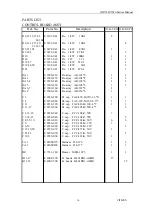
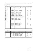
PARTS LIST
CONTROL BOARD ASSY

Ref. No.

Parts No.

Description

3546-PF/IF

3546-RF/TF

OSC 1

E 501-390

 X'tal   CST5.00MGW

1

1

S 1,2

E 5102-450

 Key switch    SKHHNH

2

2

CN 1

E 48000260

 Connector   B5P-SHF-1

1

1

CN 2

E 4800-690

 Connector   5267-02A

1

1

CN 3

E 48000265

 Connector   5045-04A

1

1

CN 4

E 48000600

 Connector   57GE40360-751

1


CN 4

E 48000280

 Connector   FCN-674J025-L/C


1

CN 5


 Connector   5267-04A

1

1

CN 6

E 48000565

 Connector   285D-9660J-101

1

1

DS 1

E 5103-520

 Dip SW.    KSD-10

1

1

DS 2

E 5103-460

 Dip SW.    SD-08ZL

1

NLCB

E 8035-010

 Cable tie

1

1

0D000002M

 Screw  M3x10 for CN4

2

0D003501

 Screw  M3x6 for IC2

2

2

02000207M

 Nut       M3 for IC2,CN4

4

02000207M    Nut       M3 for IC2

2


PCB ASSY

Parts No.

Description

3546-PF/IF

3546-RF/TF

E70010950

 iDP-3546F-PF 230V IEB

O

E70010940

 iDP-3546F-RF 230V IEB

O

E70010960

 iDP-3546F-IF 120V INB

O

E70010941

 iDP-3546F-TF 120V INB

O

Summary of Contents for iDP-3545 Series

Page 1: ...Service Manual Model iDP 3545 3546 Rev 0 00 Newly issued on Sep 22 1997 Japan CBM Corporation Information Systems Div...

Page 2: ...iDP 3545 3546 Service Manual CITIZEN 2 Contents 1 Disassembly and Assembly 3 2 Parts list 10 3 Parts Position 21 4 Circuit Diagram 25...

Page 3: ...iDP 3545 3546 Service Manual CITIZEN 3 1 Disassembly and Assembly...

Page 4: ...iDP 3545 3546 Service Manual CITIZEN 4 1 How to remove the Upper Case 1 Remove the Printer Cover 2 Unfasten 4 screws 1 M3x12 as shown in the figure and lift the Upper Case...

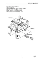
Page 5: ...in the figure 3 Lift the Printer Unit in the arrow position for removal 4 Remove the AC Cord form the Lower Case 3 How to remove the Printer Mechanism 1 Unfasten 2 screws 1 M3x14 as shown in the figur...

Page 6: ...remove the Shield plate 3 To remove the Control Board unfasten 2 screws 1 4 Disconnect some connectors as below IDP 3545 For Printer Mechanism 3 17pin 4 7pin For PE sensor 5 2pin IDP 3546 For Printer...

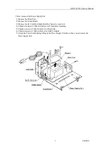
Page 7: ...ove the AC Cord Cord bush from the Chassis by some tool 4 Unfasten 2 screws 1 M4x6 which are for Transformer mounting 5 Unfasten a screw 2 M3x8 which is for Heat Sink 6 Unfasten a screw 3 M4x6 which i...

Page 8: ...r Unit 2 Remove the Printer Mechanism 3 Remove the PE sensor connector 2pin from the Control Board 4 Remove the Vinyl Tape 5 Push the Switch Holder the arrow 1 direction to remove the Hooks 3 from the...

Page 9: ...Auto Cutter AC 134 1 Remove the Upper Case 2 Remove the Binding Strap as shown in the figure by some tools 3 Disconnect the connector from the Control Board 4 Unfasten a screw 2 M2 6x6 as shown in the...

Page 10: ...iDP 3545 3546 Service Manual CITIZEN 10 2 Parts list...

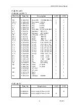
Page 11: ...4035 690 FG plate 1 1 6 E 5117 050 Switch holder 1 1 7 E 5102 480 PE Switch 1 1 8 E 5071 130 Switch knob 1 1 9 E 5101 390 PE spring 1 1 25 E 6101 115 Bush SR4N4 for 120V 1 1 26 E 6101 120 Bush SR5N4 f...

Page 12: ...iDP 3545 3546 Service Manual CITIZEN 12...

Page 13: ...iDP 3545 3546 Service Manual CITIZEN 13...

Page 14: ...2 C 5 E 2230 050 El cap FAC 228M 63V 1 1 C 6 E 2220 050 C cap FCC 101 J 50V 1 1 C 7 E 2230 060 El cap FAC 105 M 50V 1 1 C 8 E 2230 070 El cap FAC 477 M 35V 1 1 C 9 E 2230 080 El cap FAC 338 M 16V 1 1...

Page 15: ...2 IC 10 E 2010201 IC HD7406P 1 IC 12 102 E 201 811 IC HD74LS373P 2 IC 101 E 202 830 IC TA8428K 1 1 IC 103 E 101007 IC M5M28C64 1 1 XLS28C64P 150 28C64A 15P TR 1 4 101 E 359 041 Tr 2SC945P 5 TR 1 7 101...

Page 16: ...y AR 103 3 1 1 RA 6 7 E 3500 260 Re array AR 332 8 2 RA 8 E 3500 280 Re array AR 332 6 1 C 1 E 2230 200 El cap FAC 476 M 35V 6 3 11 1 1 C 2 E 2230 020 EL cap FAC 107 M 16V 6 3 7 1 1 C 11 E 2230 190 El...

Page 17: ...Connector 57GE40360 751 1 CN 4 E 48000280 Connector FCN 674J025 L C 1 CN 6 E 48000565 Connector 285D 9660J 101 1 1 DS 1 E 5103 520 Dip SW KSD 10 1 1 DS 2 E 5103 460 Dip SW SD 08ZL 1 NLCB E 8035 010 Ca...

Page 18: ...2 IC 10 E 2010201 IC HD7406P 1 IC 12 102 E 201 811 IC HD74LS373P 2 IC 101 E 202 830 IC TA8428K 1 IC 103 E 101007 IC M5M28C64 1 1 XLS28C64P 150 28C64A 15P TR 1 4 101 E 359 041 Tr 2SC945P 5 TR 1 7 101...

Page 19: ...3500 260 Re array AR 332 8 2 RA 8 E 3500 280 Re array AR 332 6 1 C 1 E 2230 200 El cap FAC 476 M 35V 6 3 11 1 1 C 2 E 2230 020 EL cap FAC 107 M 16V 6 3 7 1 1 C 11 E 2230 190 El cap FAC 226 M 16V 4 7...

Page 20: ...57GE40360 751 1 CN 4 E 48000280 Connector FCN 674J025 L C 1 CN 5 Connector 5267 04A 1 1 CN 6 E 48000565 Connector 285D 9660J 101 1 1 DS 1 E 5103 520 Dip SW KSD 10 1 1 DS 2 E 5103 460 Dip SW SD 08ZL 1...

Page 21: ...iDP 3545 3546 Service Manual CITIZEN 21 3 Parts Position...

Page 22: ...iDP 3545 3546 Service Manual CITIZEN 22 SILK DRAWING 1 PARALLEL Please refer the parts list regarding actual parts assembling location...

Page 23: ...iDP 3545 3546 Service Manual CITIZEN 23 2 SERIAL Please refer the parts list regarding actual parts assembling location...

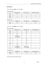
Page 24: ...2 1 2 3 4 2 iDP 3545 3546F 40RF TF 120V 230V IEA B FOR EMULATION RF CBM mode SF STAR mode TF ESC POS mode JP1 1 2 3 4 JP2 1 2 3 4 JP3 1 2 3 4 JP4 1 2 5 6 3 4 JP5 1 2 RS 232C 3 4 CURRENT 1 2 1 2 JP6 1...

Page 25: ...iDP 3545 3546 Service Manual CITIZEN 25 4 Circuit Diagram...

Page 26: ...iDP 3545 3546 Service Manual CITIZEN 26 BLOCK DIAGRAM...

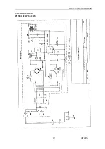
Page 27: ...iDP 3545 3546 Service Manual CITIZEN 27 CIRCUIT DIAGRAM POWER SUPPLY 120V...

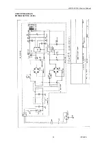
Page 28: ...iDP 3545 3546 Service Manual CITIZEN 28 CIRCUIT DIAGRAM POWER SUPPLY 230V...

Page 29: ...iDP 3545 3546 Service Manual CITIZEN 29 CIRCUIT DIAGRAM CONTROL BOARD iDP 3545 3546 PF...

Page 30: ...iDP 3545 3546 Service Manual CITIZEN 30 CIRCUIT DIAGRAM CONTROL BOARD iDP 3545 3546 RF...

Reviews: