CHAPTER 1
Disassembly,Reassembly,Maintenance
Contents
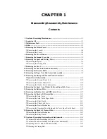
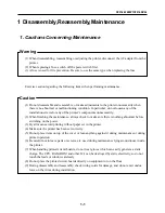
1. Cautions Concerning Maintenance ........................................................................ 1-1
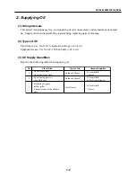
2. Supplying Oil ........................................................................................................... 1-2
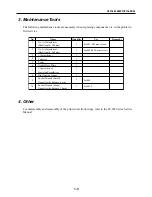
3. Maintenance Tools ................................................................................................... 1-3
4. Other ......................................................................................................................... 1-3
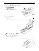
5. Removing the Printer Covers ................................................................................. 1-4
■
Removing the Cover R .......................................................................................... 1-4
■
Removing the Cover J ........................................................................................... 1-4
6. Removing the Cover Window ................................................................................. 1-4
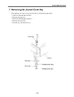
7. Removing the Journal Cover Key .......................................................................... 1-5
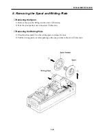
8. Removing the Spool and Writing Plate ................................................................. 1-6
■
Removing the Spool .............................................................................................. 1-6
■
Removing the Writing Plate ................................................................................... 1-6
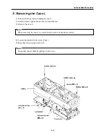
9. Removing the Case L ............................................................................................... 1-7
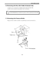
10. Removing the Near End Switch Subassembly ...................................................... 1-8
11. Removing the Pressure Roller ................................................................................ 1-8
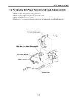
12. Removing the Paper Near End Sensor Subassembly ........................................... 1-9
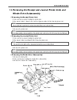
13. Removing the Receipt and Journal Printer Units and
Winder Drive Subassembly .................................................................................. 1-10
■
Removing the Receipt Printer Unit ...................................................................... 1-10
■
Removing the Journal Printer Unit ...................................................................... 1-10
■
Removing the Winder Drive Subassembly .......................................................... 1-10
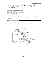
14. Removing the Spool Gear, Winder Pulley and Spool Idle Gear ........................ 1-11
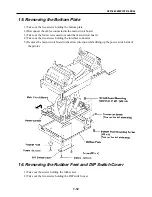
15. Removing the Bottom Plate .................................................................................. 1-12
16. Removing the Rubber Feet and DIP Switch Cover ............................................ 1-12
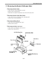
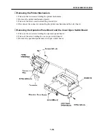
17. Removing the Bracket R (Receipt Side) .............................................................. 1-13
■
Removing the Auto Cutter ................................................................................... 1-13
■
Removing the Auto Cutter Paper Guide .............................................................. 1-13
■
Removing the Relay Board .................................................................................. 1-13
■
Removing the Cutter Lock Lever ........................................................................ 1-13
■
Removing the Printer Mechanism ....................................................................... 1-14
■
Removing the Operation Panel Board and the Cover Open Switch Board ......... 1-14
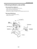
18. Removing the Bracket J (Journal Side) ............................................................... 1-15
■
Removing the Printer Mechanism ....................................................................... 1-15
■
Removing the Relay Board .................................................................................. 1-15
19. Cautions Concerning Reassembly and Adjustments .......................................... 1-16
■
Cautions When Reassembling the Case L ........................................................... 1-16
■
Cautions When Reassembling the Winder Drive Subassembly .......................... 1-17
■
Adjusting the Near End Switch Subassembly ...................................................... 1-18
■
Adjusting the Timing Belt .................................................................................... 1-19
Summary of Contents for CBM-262 Type II
Page 1: ...LINE THERMAL PRINTER MODEL CBM 262 Rev 1 00 First created June 18th 1996 Service Manual ...
Page 2: ...i REVISION Rev No Date Content Rev 1 00 June 18 1996 First created ...
Page 4: ...CHAPTER 1 DISASSEMBLY REASSEMBLY MAINTENANCE ...
Page 25: ...CHAPTER 2 CIRCUIT DIAGRAMS ...
Page 27: ...CBM 262 SERVICE MANUAL 2 1 1 INTER CONNECTION RC 232C ...
Page 28: ...CBM 262 SERVICE MANUAL 2 2 2 MAIN PCB RC 232C CPU ...
Page 29: ...CBM 262 SERVICE MANUAL 2 3 MAIN PCB RC 232C MEMORY ...
Page 30: ...CBM 262 SERVICE MANUAL 2 4 MAIN PCB RC 232C GATE ARRAY ...
Page 31: ...CBM 262 SERVICE MANUAL 2 5 MAIN PCB RC 232C PANEL CONT DRAWER ...
Page 32: ...CBM 262 SERVICE MANUAL 2 6 MAIN PCB RC 232C HEAD CONT DIP SWITCH ...
Page 33: ...CBM 262 SERVICE MANUAL 2 7 MAIN PCB RC 232C RECEIPT CONT ...
Page 34: ...CBM 262 SERVICE MANUAL 2 8 MAIN PCB RC 232C JOURNAL CONT ...
Page 35: ...CBM 262 SERVICE MANUAL 2 9 MAIN PCB RC 232C POWER ...
Page 36: ...CBM 262 SERVICE MANUAL 2 10 MAIN PCB RC 232C SERIAL I F ...
Page 37: ...CBM 262 SERVICE MANUAL 2 11 3 INTER CONNECTION CENTRONICS ...
Page 38: ...CBM 262 SERVICE MANUAL 2 12 4 MAIN PCB CENTRONICS CPU ...
Page 39: ...CBM 262 SERVICE MANUAL 2 13 MAIN PCB CENTRONICS MEMORY ...
Page 40: ...CBM 262 SERVICE MANUAL 2 14 MAIN PCB CENTRONICS GATE ARRAY ...
Page 41: ...CBM 262 SERVICE MANUAL 2 15 MAIN PCB CENTRONICS PANEL CONT DRAWER ...
Page 42: ...CBM 262 SERVICE MANUAL 2 16 MAIN PCB CENTRONICS HEAD CONT DIP SWITCH ...
Page 43: ...CBM 262 SERVICE MANUAL 2 17 MAIN PCB CENTRONICS RECEIT CONT ...
Page 44: ...CBM 262 SERVICE MANUAL 2 18 MAIN PCB CENTRONICS JOURNAL CONT ...
Page 45: ...CBM 262 SERVICE MANUAL 2 19 MAIN PCB CENTRONICS POWER ...
Page 46: ...CBM 262 SERVICE MANUAL 2 20 MAIN PCB CENTRONICS CENTRONICS I F ...
Page 47: ...CBM 262 SERVICE MANUAL 2 21 5 OPE PANE PCB ...
Page 48: ...CBM 262 SERVICE MANUAL 2 22 6 CONNECT PCB 1 ...
Page 49: ...CBM 262 SERVICE MANUAL 2 23 7 CONNECT PCB 2 ...
Page 50: ...CHAPTER 3 PARTS LISTS ...
Page 53: ...CBM 262 SERVICE MANUAL 3 2 Sample layout Main PCB RS 232C Parts side ...
Page 54: ...CBM 262 SERVICE MANUAL 3 3 Sample layout Main PCB RS 232C Soldered side ...
Page 59: ...CBM 262 SERVICE MANUAL 3 8 Sample layout Main PCB Centronics Parts side ...
Page 60: ...CBM 262 SERVICE MANUAL 3 9 Sample layout Main PCB Centronics Soldered side ...
Page 64: ...CBM 262 SERVICE MANUAL 3 13 Sample layout Ope Pane PCB Parts side Soldered side ...
Page 67: ...CBM 262 SERVICE MANUAL 3 16 Sample layout Connect PCB 1 Parts side Soldered side ...
Page 70: ...CBM 262 SERVICE MANUAL 3 19 Sample layout Connect PCB 2 Parts side Soldered side ...
Page 73: ...CBM 262 SERVICE MANUAL 3 22 Drawing No 1 General Assembly ...
Page 76: ...CBM 262 SERVICE MANUAL 3 25 Drawing No 2 Mechanism Unit ...
Page 79: ...CBM 262 SERVICE MANUAL 3 28 Drawing No 3 Electrical Component Unit RS 232C I F Centronics I F ...
Page 83: ...CHAPTER 4 APPENDIX ...
Page 84: ...CHAPTER 4 Appendix Contents External View 4 1 ...


