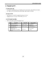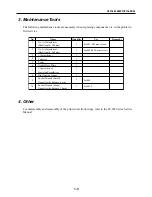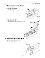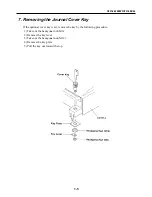
CBM-262 SERVICE MANUAL
1-16
19. Cautions Concerning Reassembly and Adjustments
Reassembly is done by following the disassembly procedure in reverse order. However, observe
the following cautions during reassembly.
■
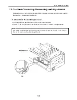
Cautions When Reassembling the Case L
1) Set the printer mechanism’s head up lever in the head down state.
2) Insert the near end cable in the slit on the rear of the case L as shown in the illustration.
Note
If assembled with the cable not inserted in the slit, the near end cable could be pinched and be
broken. Be sure to run the cable through the slit.
Summary of Contents for CBM-262 Type II
Page 1: ...LINE THERMAL PRINTER MODEL CBM 262 Rev 1 00 First created June 18th 1996 Service Manual ...
Page 2: ...i REVISION Rev No Date Content Rev 1 00 June 18 1996 First created ...
Page 4: ...CHAPTER 1 DISASSEMBLY REASSEMBLY MAINTENANCE ...
Page 25: ...CHAPTER 2 CIRCUIT DIAGRAMS ...
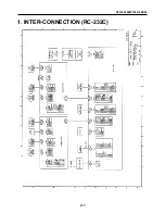
Page 27: ...CBM 262 SERVICE MANUAL 2 1 1 INTER CONNECTION RC 232C ...
Page 28: ...CBM 262 SERVICE MANUAL 2 2 2 MAIN PCB RC 232C CPU ...
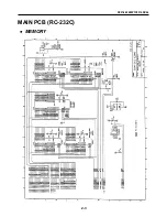
Page 29: ...CBM 262 SERVICE MANUAL 2 3 MAIN PCB RC 232C MEMORY ...
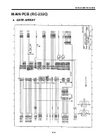
Page 30: ...CBM 262 SERVICE MANUAL 2 4 MAIN PCB RC 232C GATE ARRAY ...
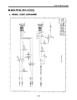
Page 31: ...CBM 262 SERVICE MANUAL 2 5 MAIN PCB RC 232C PANEL CONT DRAWER ...
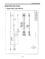
Page 32: ...CBM 262 SERVICE MANUAL 2 6 MAIN PCB RC 232C HEAD CONT DIP SWITCH ...
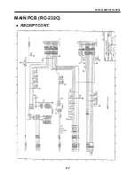
Page 33: ...CBM 262 SERVICE MANUAL 2 7 MAIN PCB RC 232C RECEIPT CONT ...
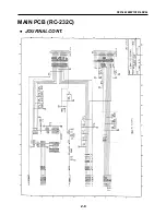
Page 34: ...CBM 262 SERVICE MANUAL 2 8 MAIN PCB RC 232C JOURNAL CONT ...
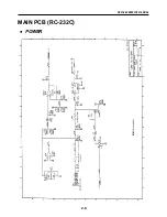
Page 35: ...CBM 262 SERVICE MANUAL 2 9 MAIN PCB RC 232C POWER ...
Page 36: ...CBM 262 SERVICE MANUAL 2 10 MAIN PCB RC 232C SERIAL I F ...
Page 37: ...CBM 262 SERVICE MANUAL 2 11 3 INTER CONNECTION CENTRONICS ...
Page 38: ...CBM 262 SERVICE MANUAL 2 12 4 MAIN PCB CENTRONICS CPU ...
Page 39: ...CBM 262 SERVICE MANUAL 2 13 MAIN PCB CENTRONICS MEMORY ...
Page 40: ...CBM 262 SERVICE MANUAL 2 14 MAIN PCB CENTRONICS GATE ARRAY ...
Page 41: ...CBM 262 SERVICE MANUAL 2 15 MAIN PCB CENTRONICS PANEL CONT DRAWER ...
Page 42: ...CBM 262 SERVICE MANUAL 2 16 MAIN PCB CENTRONICS HEAD CONT DIP SWITCH ...
Page 43: ...CBM 262 SERVICE MANUAL 2 17 MAIN PCB CENTRONICS RECEIT CONT ...
Page 44: ...CBM 262 SERVICE MANUAL 2 18 MAIN PCB CENTRONICS JOURNAL CONT ...
Page 45: ...CBM 262 SERVICE MANUAL 2 19 MAIN PCB CENTRONICS POWER ...
Page 46: ...CBM 262 SERVICE MANUAL 2 20 MAIN PCB CENTRONICS CENTRONICS I F ...
Page 47: ...CBM 262 SERVICE MANUAL 2 21 5 OPE PANE PCB ...
Page 48: ...CBM 262 SERVICE MANUAL 2 22 6 CONNECT PCB 1 ...
Page 49: ...CBM 262 SERVICE MANUAL 2 23 7 CONNECT PCB 2 ...
Page 50: ...CHAPTER 3 PARTS LISTS ...
Page 53: ...CBM 262 SERVICE MANUAL 3 2 Sample layout Main PCB RS 232C Parts side ...
Page 54: ...CBM 262 SERVICE MANUAL 3 3 Sample layout Main PCB RS 232C Soldered side ...
Page 59: ...CBM 262 SERVICE MANUAL 3 8 Sample layout Main PCB Centronics Parts side ...
Page 60: ...CBM 262 SERVICE MANUAL 3 9 Sample layout Main PCB Centronics Soldered side ...
Page 64: ...CBM 262 SERVICE MANUAL 3 13 Sample layout Ope Pane PCB Parts side Soldered side ...
Page 67: ...CBM 262 SERVICE MANUAL 3 16 Sample layout Connect PCB 1 Parts side Soldered side ...
Page 70: ...CBM 262 SERVICE MANUAL 3 19 Sample layout Connect PCB 2 Parts side Soldered side ...
Page 73: ...CBM 262 SERVICE MANUAL 3 22 Drawing No 1 General Assembly ...
Page 76: ...CBM 262 SERVICE MANUAL 3 25 Drawing No 2 Mechanism Unit ...
Page 79: ...CBM 262 SERVICE MANUAL 3 28 Drawing No 3 Electrical Component Unit RS 232C I F Centronics I F ...
Page 83: ...CHAPTER 4 APPENDIX ...
Page 84: ...CHAPTER 4 Appendix Contents External View 4 1 ...

