background image

CBM-230/231 Service Manual

  CITIZEN

6

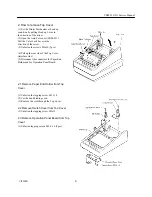
3.Remove Mech. Bracket Unit

(1) Unfasten the screws M3x7 (2pcs).
(2) Remove the connectors of Auto Cuter and
   Printer Mechanism (2pcs).
(3) Release the Lock of flexible cable and
   remove the flexible cable.

3.1 Remove Auto Cutter from Mech. Bracket
(CBM-231)

(1)Unfasten only one screwM2x6.
  (Mech. Bracket has two M2.3 x 6 screws.)
(2)Remove the cord through Mech. Bracket

3.2 Remove Printer Mechanism from Mech.
Bracket

(1) Unfasten the crews M2 x 6 (2pcs).
(2) Pulling Auto Cuter unit aslant into
   the upside.

3.3 Remove Head Up Lever from Mech.
Bracket (CBM-231)

(1) Moving the Head Up Lever in the  direction  of
the arrow, remove the Head up lever.

3.4 Remove Cutter Lock Lever from
Mech. Bracket (CBM-231)

(1) Unfasten the screw M2.6 x 6.

3.5 Remove Paper Cutter from Printer
Mechanism


(CBM-230)

(1) Unfasten the screws M2 x6 (2pcs).

3.6 Remove FG Plate from Printer
Mechanism

(1)


Unfasten the screw M2x6.

Summary of Contents for CBM-230

Page 1: ...CITIZEN Service Manual Model CBM 230 231 Japan CBM Corporation Information Systems Div ...

Page 2: ... 3 3 Remove Head Up Lever from Mech Bracket CBM 231 6 3 4 Remove Cutter Lock Lever from Mech Bracket CBM 231 6 3 5 Remove Paper Cutter from Printer Mechanism CBM 230 6 3 6 Remove FG Plate from Printer Mechanism 6 4 Remove Control Board 7 5 Remove Power Box 7 6 Remove Switching Box 8 2 Circuit Diagram 9 Block Diagram 10 Circuit Diagram Serial Interface 11 Circuit Diagram Parallel Interface 12 Circu...

Page 3: ...CBM 230 231 Service Manual CITIZEN 3 1 Assembling Disassembling procedure ...

Page 4: ...CBM 230 231 Service Manual CITIZEN 4 1 How to remove Printer Cover 1 Open the Printer cover 2 Pulling the Hook into inner side remove the Printer Cover ...

Page 5: ...n the screws M3x10 2pcs 4 Pull up the rear side of the Top Cover interface side 5 Disconnect the connectors for Paper End Holder and for Operation Panel Board 2 1 Remove Paper End Holder from Top Cover 1 Unfasten the tapping screw M3 x 14 2 Cut the band binding cord 3 Remove the cord through the Top Cover 2 2 Remove Switch Cover from Top Cover 1 Unfasten the tapping screw M3x12 2 3 Remove Operatio...

Page 6: ...s 2 Remove the cord through Mech Bracket 3 2 Remove Printer Mechanism from Mech Bracket 1 Unfasten the crews M2 x 6 2pcs 2 Pulling Auto Cuter unit aslant into the upside 3 3 Remove Head Up Lever from Mech Bracket CBM 231 1 Moving the Head Up Lever in the direction of the arrow remove the Head up lever 3 4 Remove Cutter Lock Lever from Mech Bracket CBM 231 1 Unfasten the screw M2 6 x 6 3 5 Remove P...

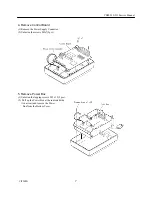
Page 7: ... Control Board 1 Remove the Power Supply Connector 2 Unfasten the screws M3x7 2pcs 5 Remove Power Box 1 Unfasten the tapping screws M3 x 12 2pcs 2 Pull up the Power Box at the indicated side An arrow and remove the Power Box from the Bottom Cover ...

Page 8: ... the Bush using a tool 2 Unfasten the Earth screws M4 x 6 and M 3 x 6 remove the Earth Cord 3 Unfasten the screws M3 x 7 4pcs 4 Pulling up the Power Supply Switch remove the Switching Power Supply 5 Pulling the center of Shield plate remove the Shield Plate CBM 230 only ...

Page 9: ...CBM 230 231 Service Manual CITIZEN 9 2 Circuit Diagram ...

Page 10: ...CBM 230 231 Service Manual CITIZEN 10 Block Diagram ...

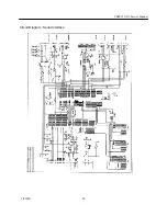
Page 11: ...CBM 230 231 Service Manual CITIZEN 11 Circuit Diagram Serial Interface ...

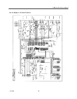
Page 12: ...CBM 230 231 Service Manual CITIZEN 12 Circuit Diagram Parallel Interface ...

Page 13: ...CBM 230 231 Service Manual CITIZEN 13 Circuit Diagram OP PCB Assy ...

Page 14: ...CBM 230 231 Service Manual CITIZEN 14 Circuit Diagram PE PCB Assy ...

Page 15: ...CBM 230 231 Service Manual CITIZEN 15 3 Service Parts List ...

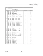
Page 16: ... CBM 230 RF UL 1 E 70010680 PCB Assy CBM 231 PF 1 E 70010690 PCB Assy CBM 231 RF 1 E 70010691 PCB Assy CBM 231 RF UL 1 15 E 66000170 Printer LT 380 1 1 18 E 4035 710 FG Plate 50 0146 1 1 19 E 6220 530 Paper Cutter 1 1 20 E 6601 290 Printer Bracket 50 0143 1 1 22 E 8000 090 Auto Cutter AC 131 1 1 23 E 8010 180 Mouth Plate F 50 0144 1 1 24 E 8010 190 Mouth Plate R 50 0143 1 1 26 E 8032 060 Head Up L...

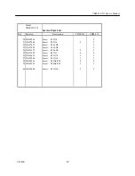
Page 17: ...M 231 50 23G58244 Screw M2X3 4 51 23G57466 Screw M2X6 5 3 52 23G57473 Screw M2 3X5 2 53 23G57481 Screw M2 6X6 1 54 23G23179 Screw M2 6X6 2 2 55 23G53585 Screw M3X7 6 8 56 23G38619 Screw M3X12 3 3 57 23G29560 Screw M3X14 1 1 58 23G42966 Screw M3X6 TW 2 2 59 23G42959 Screw M4X6 TW 1 1 60 23G22530 Screw M3X10 2 2 ...

Page 18: ...CBM 230 231 Service Manual CITIZEN 18 CBM 230 231 DISASSEMBLING DRAWING ...

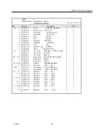
Page 19: ...TA8428K CBM 231 Only 1 2 E 390 140 Tr Array STA301A 1 3 E 202 890 Tr Array LB1650 1 TR 1 5 6 E 359 278 Transistor 2SC2785HF 2SC1740SR 3 2 E 358 040 Transistor RN1002 1 4 E 358 050 Transistor 2SJ139 1 D 1 8 10 E 400 580 Diode MPG06B RLI4002 9 11 E 3221 041 Resistor 1 4W 220 J 1 OSC 1 E 501 320 Resonator CSA25 00MX040 1 2 E 501 330 Resonator CST16 00MXW040 1 R 1 9 E 3181 041 Resistor 1 4W 180 J 2 2 ...

Page 20: ...p DD106 63F103Z50 1 11 E 2220 110 C Cap DD104 63B102K50 1 12 E 2220 120 C Cap DD104 63B471K50 1 CA 1 E 2000 070 Cap Array B5RC0124 33N 1 CN 1 E 4800 915 Connector 5267 05A X 1 2 E 48000610 Connector 5597 30CPB 1 3 E 48000615 Connector 53047 0410 1 4 E 48000620 Connector 5268 06A X 1 5 E 4800 950 Connector 5267 03A X 1 6 E 48000530 Connector TM5RJ3 66 1 7 E 48000630 Connector 5268 04A X CBM 231 Onl...

Page 21: ...CBM 230 231 Service Manual CITIZEN 21 ...

Page 22: ...Tr Array TA8428K CBM 231 Only 1 2 E 390 140 Tr Array STA301A 1 3 E 202 890 Tr Array LB1650 1 TR 1 5 6 E 359 278 Transistor 2SC2785HF 2SC1740SR 3 2 E 358 040 Transistor RN1002 1 4 E 358 050 Transistor 2SJ139 1 D 1 8 10 E 400 580 Diode MPG06B RLI4002 9 11 E 3221 041 Resistor 1 4W 220 J 1 OSC 1 E 501 320 Resonator CSA25 00MX040 1 2 E 501 330 Resonator CST16 00MXW040 1 R 1 9 E 3181 041 Resistor 1 4W 1...

Page 23: ...E 2220 090 C Cap DD104 63CH050C50 2 10 E 2220 100 C Cap DD106 63F103Z50 1 11 14 E 2220 110 C Cap DD104 63B102K50 2 12 13 E 2220 120 C Cap DD104 63B471K50 2 CA 1 E 2000 070 Cap Array B5RC0124 33N 1 CN 1 E 4800 915 Connector 5267 05A X 1 2 E 48000610 Connector 5597 30CPB 1 3 E 48000615 Connector 53047 0410 1 4 E 48000620 Connector 5268 06A X 1 5 E 4800 950 Connector 5267 03A X 1 6 E 48000530 Connect...

Page 24: ...CBM 230 231 Service Manual CITIZEN 24 ...

Page 25: ...ts List CBM 230 231 230 03 Ref Parts No Description QTY LED 1 E 480 290 LED SEL2310E 1 2 3 E 480 330 LED SEK2210S 2 SW 1 E 5102 490 Switch SKHHBV 1 2 E 5102 500 Switch D3C 2220 1 R 1 E 3221 041 Resistor 1 4W 220 J 1 2 3 E 3471 041 Resistor 1 4W 470 J 2 E 4900 070 Harness 25 0255 1 ...

Page 26: ...CBM 230 231 Service Manual CITIZEN 26 ...

Page 27: ...CBM 230 231 Service Manual CITIZEN 27 ...

Page 28: ...CBM 230 231 Service Manual CITIZEN 28 ...

Reviews: