background image

Page 1

OWNER'S MANUAL

190 lb. HD LAUNDRY DRYER

Cissell Manufacturing Co.

831 S.  First St. - P.O.Box 32270 - Louisville, Ky. - 40232-2270
Tel: (502) 587-1292 - Fax: (502) 585-2333 -
Sales Fax: (502) 585-3625 - Service/Parts Fax: (502) 681-1275

THIS  MANUAL  MUST  BE  GIVEN  TO  THE  EQUIPMENT  OWNER

MAN HD190   2/03

HD190

Gas: Natural and LP

Steam

Summary of Contents for HD190

Page 1: ... Manufacturing Co 831 S First St P O Box 32270 Louisville Ky 40232 2270 Tel 502 587 1292 Fax 502 585 2333 Sales Fax 502 585 3625 Service Parts Fax 502 681 1275 THIS MANUAL MUST BE GIVEN TO THE EQUIPMENT OWNER MAN HD190 2 03 HD190 Gas Natural and LP Steam ...

Page 2: ... gas supplier from a neighbor s phone Follow the gas supplier s instructions If you cannot reach your gas supplier call the fire department Installation and service must be performed by a qualified installer service agency or the gas supplier WARNING In the event the user smells gas odor instructions on what to do must be posted in a prominent location This information can be obtained from the loc...

Page 3: ...s wrinkles from setting in and reduces the possibility of spontaneous combustion WARNING Be safe shut main electrical power and gas supply off externally before attempting service WARNING Never use drycleaning solvents gasoline kerosene or other flammable liquids in the dryer FIRE AND EXPLOSION WILL OCCUR NEVER PUT FABRICS TREATED WITH THESE LIQUIDS INTO THE DRYER NEVER USE THESE LIQUIDS NEAR THE ...

Page 4: ...ment ou vous vous trouvez Evacuez la piece le batiment ou la zone Appelez immediatement votre fournisseur de gaz depuis un voisin Suivez les instructions du fournisseur Si vous ne pouvez rejoindre le fournisseur de gaz appelez le service des incendies __ l installation et l entretien doivent etre assures par un installateur ou un service d entretien qualifie ou par le fournisseur de gaz ATTENTION ...

Page 5: ...tall to diagnose troubles to adjust remove or replace defective equipment or a part nor does it include any responsibility for transportation expense which is involved therein The warranty of Cissell is contingent upon installation and use of its equipment under normal operating conditions The warranty is void on equipment or parts that have been subjected to misuse accident or negligent damage op...

Page 6: ...els 38 39 Direct Spark Ignition Operation 40 41 GeneralMaintenance 42 43 Shimming the Basket and Spider Assembly 44 46 AirSwitchAdjustment 47 Pulley and Belt Maintenance 48 Front of Dryer Parts 49 Rear of Dryer Parts 50 51 Front Panel and Door Assembly 52 Lint Door Assembly 53 DMPControlAssembly 54 55 Two Timer Control Box Assembly 56 57 PROHC Control Panel Assembly 58 DMP Sensor Assembly 59 Two T...

Page 7: ...oucher Caliente no tocar Heet Niet Aanraken dangerous voltage tension dangereuse Gafahrliche elektrische Spannung tension peligrosa on marche Ein conectado off arrêt Aus desconectado start demarrage Start arranque de un movimiento emission of heat in general êmission de chaleur en general Warmeabgabe allgemein emisión de calor cooling refroidissement Kuhlen enfriamiento ...

Page 8: ...directions rotation dans les deux sens Drehbewigung in zwei Richtungen movimiento rotativo en los dos sentidos direction of rotation sens de mouvement continu de rotation Drehbewegung in Pfeilrichtung movimiento giratorio o rotatorio en el sentido de la flecha End of Cycle caution attention Achtung atencion precaucion ...

Page 9: ... amperes on rating plate before installing the dryer Leveling Use spirit level on top of dryer The use of shims are acceptable for this procedure IMPORTANT Before installing or operating this dryer thoroughly read the owner s manual for correct instructions concerning electric connections exhaust ducting gas piping steam connections make up air etc IMPORTANT Read the warnings in this manual IMPORT...

Page 10: ...signed that when an operator opens the dryer door the basket and exhaust fan stop Hot dry air is properly and effectively moved through the basket and exhausted through a lint trap to the venting and eventually to the atmosphere The lint accumulates in the collector and should be removed as needed minimum once daily IMPORTANT Provide adequate clearance for air openings into the combustion chamber ...

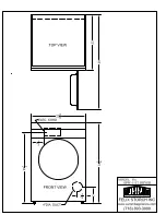
Page 11: ...Page 11 190 LB GAS DRYER SPECIFICATIONS ILLUSTRATION ALL DIMENSIONS ARE 1 4 6 4 MM AND ARE SUBJECT TO CHANGE WITHOUT NO TICE REAR VIEW ...

Page 12: ...Page 12 190 LB GAS DRYER SPECIFICATIONS ILLUSTRATION REAR VIEW DIMENSIONS REAR COVER NOT SHOWN TOP VIEW DIMENSIONS ALL DIMENSIONS ARE 1 4 6 4 MM AND ARE SUBJECT TO CHANGE WITHOUT NO TICE ...

Page 13: ...Page 13 190LB STEAM DRYER SPECIFICATIONS ILLUSTRATION ALL DIMENSIONS ARE 1 4 6 4 MM AND ARE SUBJECT TO CHANGE WITHOUT NO TICE REAR VIEW ...

Page 14: ...Page 14 190 LB STEAM DRYER SPECIFICATIONS ILLUSTRATION ALL DIMENSIONS ARE 1 4 6 4 MM AND ARE SUBJECT TO CHANGE WITHOUT NO TICE TOP VIEW DIMENSIONS REAR VIEW DIMENSIONS REAR COVER NOT SHOWN ...

Page 15: ...uct 12 3048 mm dia Maximum Air Displacement 2 780 cfm 4726 m3 h Recomm Oper Range 2 300 cfm 3910 m3 h Gas Net Weight 2 075 lb 941 kg Steam Net Weight 2 205 lb 1000 kg Gas Shipping Weight 2 225 lb 1009 kg Steam Shipping Weight 2 355 lb 1068 kg Shipping Dimensions 89 1 2 H x 58 W x 84 1 2 D 2273 x 1473 x 2146 mm Crating Volume 232 ft 6 57m Gas Supply 1 1 4 DN32 pipe connection 1 1 4 SPT Input Rating...

Page 16: ...2 reversals per minute Non Reversing 30 rpm Exhaust Duct 12 3048 mm dia Maximum Air Displacement 2780 cfm 4726 m h Recomm Oper Range 2300 cfm 3910 m h Net Weight 1800 lb 816 kg Shipping Weight 1950 lb 885 kg Shipping Dimensions 89 1 2 H x 58 W x 84 1 2 D 2273 x 1473 x 2146 mm Crating Volume 232 ft 6 57 m Input Rating 15 7 BHP 132 000 kcal h Pressure 125 psi max Steam Supply Connection 1 1 4 SPT DN...

Page 17: ...d it is only necessary for the electrician to connect the power leads to the wire connectors with the service connection box on the rear of the dryer Do not connect the dryer to any voltage or current other than that specified on the dryer rating plate Wiring diagram is located on rear wall of dryer All panels must be in position before operation of dryer CAUTION Label all wires prior to disconnec...

Page 18: ...ket MTR296 380 60 3 2 4 2 4 6 1725 Basket MTR292 220 380 50 3 2 6 4 3 7 1425 Basket MTR292 240 415 50 3 2 6 4 3 7 1425 Basket MTR309 208 240 60 3 5 13 0 3450 Fan MTR291 480 60 3 5 7 1 1725 Fan MTR298 240 50 3 5 8 4 1425 Fan MTR298 380 60 3 5 17 2 16 8 1725 Fan MTR293 220 380 50 3 5 6 05 12 1 1425 Fan MTR293 240 415 50 3 5 6 05 12 1 1425 Fan ...

Page 19: ...300000 330000 350000 380000 400000 430000 450000 480000 504000 550000 605000 650000 705000 750000 806000 850000 907000 960000 1000000 3 4 3 4 3 4 3 4 3 4 3 4 1 1 1 1 1 4 1 1 4 1 1 2 1 1 2 1 1 2 2 2 2 2 2 2 2 2 2 2 1 2 2 1 2 2 1 2 2 1 2 2 1 2 2 1 2 2 1 2 2 1 2 3 3 3 3 3 3 4 3 4 3 4 1 1 1 1 1 1 1 4 1 1 4 1 1 2 1 1 2 2 2 2 2 2 2 2 1 2 2 1 2 2 1 2 2 1 2 2 1 2 2 1 2 2 1 2 2 1 2 3 3 3 3 3 3 3 1 2 3 1 2 ...

Page 20: ...Page 20 Gas Piping Installation Illustration ...

Page 21: ... 5 kPa The dryer must be isolated from the gas supply piping system by closing its individual manual shutoff valve during any pressure testing of the gas supply piping system at test pressures equal to or greater than 1 2 psi 3 5 kPa CAUTION Low gas pressure and intermittent gas will cause gas ignition problems This will cause inadequate drying of the clothes load NATURAL GAS ONLY Check the gas pr...

Page 22: ...Page 22 Steam Piping Installation Illustration INDIVIDUALLYTRAPPED COILSARE RECOMMENDED RATHER THAN MANFOLDING RETURN INTO ONE TRAP ...

Page 23: ...on 5 Before connecting trap and check valve to dryer open globe valve in steam supply line and allow steam to flow through dryer to flush out any dirt and scale from dryer This will assure proper operation of trap when connected 6 After flushing system install bucket trap with built in strainer and check valve For successful operation of dryer install trap 18 below coil and as near to the dryer as...

Page 24: ...Page 24 Dryer Installation with Multiple Exhaust Illustration ...

Page 25: ...ates the dryer air from room comfort air If dryers use room air instead of outside air the heat loss can be another 25 Btu h for each cubic foot per minute cfm used 4 Heat loss into laundry room from dryer fronts only is about 60 Btu h per square foot 5 Flange mounted belt driven tube axial fan Fan must be run when one or more dryers are running See suggested Automatic Electrical Control Wiring Di...

Page 26: ...s Duct Diameter in inches in cm No of Dryers Duct Diameter in inches in cm No of Dryers Duct Diameter in inches in cm 1 2 3 4 5 6 7 8 9 10 11 12 13 14 15 16 17 18 19 20 21 22 23 24 6 9 11 12 14 15 16 17 18 19 20 21 22 23 23 24 25 26 26 27 28 28 29 30 15 23 27 30 35 38 41 43 46 48 51 53 56 58 58 61 63 66 66 68 71 71 73 76 1 2 3 4 5 6 7 8 9 10 11 12 13 14 15 16 17 18 19 20 21 22 23 24 8 12 14 16 18 ...

Page 27: ... or side walls The area of the opening should be equal to 4 to 6 times the sum of the dryer duct areas Provide 1 square foot for each 6 inches diameter 2 square feet for each 8 inches diameter and 4 square feet for each 12 inches diameter 2 Enclosure plenum with service door This separates the dryer air from the room comfort air If dryers use room air instead of outside air additional heat loss ca...

Page 28: ...90º bends 2 Use 45º and 30º elbows wherever possible 3 Exhaust each dryer separately 4 Do not install wire mesh or other restrictions in the exhaust duct 5 Use clean outs in the exhaust duct and clean periodically when needed 6 Never exceed 0 6 inches water column static pressure in the exhaust duct 7 Inside surface of the duct must be smooth 8 Recommend pop rivets for duct assembly FOR BEST DRYIN...

Page 29: ...elts are adjustable for belt length Please take links out to tighten fan belt This may need to be done after dryer has been running for several days If fan seems to be vibrating excessively this may be an indication that the fan belt needs to be tightened Link Belts ...

Page 30: ...d possible fire Never dry the above items in the dryer 4 Never let children play near or operate the dryer Serious injury will occur if a child should crawl inside and the dryer is turned on 5 Never use the dryer door opening and top or the lint drawer as a step stool 6 Read and follow manufacturer s instructions on packages of laundry and cleaning aids Heed any warnings or precautions 7 Never tum...

Page 31: ... and higher operating costs 2 Operate dryer using full size loads Very large loads use extra energy Very small loads waste energy 3 Dry lightweight fabrics separately from heavy fabrics You ll use less energy and get more even drying results by drying fabrics of similar weight together 4 Clean the lint screen after each load A clean lint screen helps give faster more economical drying 5 Don t open...

Page 32: ...OTSATISFACTORILYDRY 1 Timed cycle Did you allow enough heating time before the cool down part of the cycle 2 Is the lint screen blocked 3 Is the exhaust duct to the outside clean and not blocked A blocked exhaust will cause slow drying and other problems 4 For Moisture Control models Was the moisture level setting incorrect Too high GAS DRYER IGNITION Refer to the page on Instructions for the Dire...

Page 33: ...secondary voltage on transformer and check wiring and wiring diagram May be broken or defective high voltage lead Module not receiving correct input to ignite See pages 35 36 for Direct Spark Ignition process Make sure ignition module ground wire is securely grounded to the machine both sides Check continuity across unplugged valve If defective replace coil assembly Turnmanualgasvalve ON V Belt br...

Page 34: ...th a vacuum U gauge by removing a sheet metal screw in the back panel or right panel at front bottom corner and inserting the rubber tube of the vacuum gauge into screw opening See air switch adjustment sheet in service section of manual Check continuity across contacts opened and closed If defective replace switch with power off Check manifold pressure and adjust to pressure specified on rating p...

Page 35: ... for recommended sizes Check for and remove obstructions or lint build up from duct work Never use smaller size exhaust duct Always use larger size exhaust duct When flame or heat is passed over thermostat circuit should open Audible click will usually be heard If continuity remains thermostat is defective Replace thermostat Defective thermostat Defective safety overload thermo stat Lint compartme...

Page 36: ...s Clean lint accumulation on and around motors Motors should not be covered with or filled with lint Close door Adjust switch by removing cover and bend actuator lever to clear switch button 3 8 with cover in place Check continuity across switch with power off in closed and open switch If no continuity replace switch Push in contactor trip button If motor starts check voltage going to pull in sole...

Page 37: ...and clean thoroughly if heavily clogged Check piping per steam installation instructions Check trap for size and capacity If dirty and sluggish clean thoroughly or replace Check return line for high back pressure or another trap charging against the trap functioning improperly Check voltage to damper motors Adjust dampers to close when calling for heat Defective timer Valve closed Steam trap block...

Page 38: ...Page 38 Two Timer Models Figures 1 2 and 3 Illustrations ...

Page 39: ... figure 3 6 Turn switch to start position See figure 1 7 Close the dryer door but the basket will not rotate until the PUSH TO START BUTTON is pressed Press in the PUSH TO START BUTTON approximately 2 seconds until the dryer starts running and then release button See figure 1 What is happening to the drying operation a The fan motor will operate b The basket will rotate c The heat source will be e...

Page 40: ... and no flame is detected the gas valve is de energized and the module goes into an interpurge delay After this delay the module will attempt another trial for ignition period This will continue until the number of retries has been used up At that time the module will go into safety lockout 4 Recovery from safety lockout requires one of the following a A manual reset by opening and closing the loa...

Page 41: ...1 D Under basket and burner housing thermal safety switches 2 E Variable thermostat 1 F Push to start switch 1 THERMOSTAT CALLS FOR HEAT IGNITION CYCLE BE GINS GAS VALVE ON MAIN BURNER FLAME DETECTED CONTROL LOC OUT RESET POWER REQUIRESAMANUAL RESET Opening closing door power switch ON OFF SPARK IGNITION OFF FLAME MONITOR ON GASVALVE ON FLAME IS LOST DUE TO POWER OUTAGE DOOR OPEN NO YES NO FLAME I...

Page 42: ...he motor mounting bracket on the back at the dryer The fan belt is adjusted by removing links in the belt 4 ELECTRIC MOTORS Keep motors clean and dry Motors having ball bearings are packed with sufficient grease for approximately five years of normal operation After five years the bearings and housing should be cleaned thoroughly Repack each bearing and the cavity in back of the bearing on third f...

Page 43: ...ations on separate page 8 EXHAUST SYSTEM Periodically check and clean 9 VOLTAGE Voltage should be checked periodically per rating plate located on rear wall of dryer 10 COMBUSTION MAKE UP AND VENTILATING AIR The flow should not be obstructed 11 DRYER AREA Keep dryer area clean of lint and free from combustible materials gasoline and other flammable liquids vapors MAINTENANCE ...

Page 44: ...hims under B 1 Loosen bolts on bearing A 2 Add shim s under bearing A 3 Tighten bolts check alignment 4 Repeat until aligned BASKET TOO HIGH If there are shims under A 1 Loosen bolts 2 Remove shim s 3 Tighten bolts check alignment If there are no shims under A 1 Loosen bolts on bearing B 2 Add shim s under bearing B 3 Tighten bolts check alignment 4 Repeat until aligned ...

Page 45: ...Page 45 Shimming the Basket and Spider Assembly Illustration ...

Page 46: ...C Mark this position and the nearest rib to this position If it is between two ribs both ribs may need to be shimmed D Remove the basket from the dryer do not loosen the alignmentbolts E With the basket on the floor spider up loosen the cap screws and tie rod nuts enough to insert one or two shims between the spider leg and the basket at the marked position With shims in place tighten the screws a...

Page 47: ... hold switch mounting bracket firmly and adjust switch actuator D with needle nose pliers at E by twisting actuator right or left whichever is needed so that switch closes when end of air blade engages bar C 4 Maximum opening of air switch must be no greater than 3 4 figure 3 Bend tab F in or out to maintain this dimension 5 Re install air switch assembly on rear of dryer 6 Re check operation of a...

Page 48: ...dryer into operation ensure that the drive belts and pulleys are in good condition and have sufficient belt tension Check belt tension after dryer is in operation 2 3 weeks Tighten as necessary Check belt tensions and belt pulley condition every 3 6 months DRIVE PULLEYS AND BELTS ...

Page 49: ...UX548 JACKET WELDEDASM 5 TU14360 FRONT PANELASM 6 TUX572 LINT SCREEN 7 TUX103 BASKETASM 8 TUX579 SIDE VALANCE 9 TU14490 FRONT VALANCE 10 TU14537 LINT DOORASM 11 TU14542 DMP CONTROLASM 12 TU3246 3 8 16 SCREW 13 TU6854 14 S M SCREW 14 TU7733 8 SELF DRILL SCREW 15 VSB134 3 8 LOCK WASHER 16 TU14924 SKIRT OPTIONAL 17 TUX531 SPIDER WELDMENT ...

Page 50: ...Page 50 190 LB LAUNDRY DRYER REAR EXPLODED VIEW ...

Page 51: ...U7733 SCREW SELF DR 8 18X1 2 12 TUX195 COVER MTR CTRL BOX 13 TU8206 AIR SWITCH 14 TU14765 REV CTRL PNL 15 TU14675 IGN MODULE C E GA 00765 0 IGN MODULE NON C E PARTS 190 LB LAUNDRYDRYER REAR 16 GA 00803 0 DSI CABLE GAS ONLY 17 GREENFIELD CABLE 18 TUX577 5 8 KEY 19 TUX603 BELT DOUBLE V 46 LG 20 TU15508 SHEAVE 8 9 O D 60 Hz TUX602 SHEAVE 50 Hz 21 TUX594 GEAR REDUCER 22 TU15506 TAPER BUSHING 23 TUX595...

Page 52: ... 7 TU2686 8 32 Pan Hd screw 8 TU2687 8 Ph Hd screw 9 TU2836 5 16 18 H H screw 10 TU3209 14 Pan Hd screw 11 TU3212 5 16 Lock washer 12 TU3785 8 E T Cup washer Ref No Part No Description 13 TU5503 Door latch spacer 14 TU7169 Gasket 15 TU15107 Door glass 20 1 4 16 TUA2319H Door latch w keeper 17 TU5288 Door gasket 18 TU2641 Thermometer gasket 19 TU5458 Temperature label 20 TU6030 Thermostat asm see d...

Page 53: ...DOORASSEMBLY 1 LA 00124 0 LATCH 2 SB 00836 0 PANCAKE SCREW 3 SB 00949 0 FASTENER 4 TU14357 LINT DR W A 5 TU14529 HANDLE 6 TU14530 BUMPER 7 TU14594 LABEL ENGLISH 7a TU15410 LABEL 5 LANGUAGE 8 TU14640 TRIM KICKPLATE ...

Page 54: ...4 1 4 BRASS WASHER 4 TU13621 CTRL BOX 5 TU14404 DMPCONTROL 6 TU14405 OVERLAY 7 TU14435 EMERGENCY STOP 8 TU14469 DMP PANEL 9 TU14470 DMP CTRL PNL 10 TU2842 10 32 HEX NUT 11 TU3209 14 S M SCREW 12 TU3400 6 32 NUT 13 TU3479 10 32 TRUSS SCR 14 TU7848 TINNERMAN CLIP CONSIST OF ITEM S 2 5 6 7 8 12 ...

Page 55: ...l PanelAssembly Ref No PartNo Description 1 M270 Lock washer internal tooth 2 TU12253 Stud 3 TU14437 Buzzer Optional 4 TU14404 DMP Control board 5 TU15184 Overlay 6 TU14435 EmergencyStop 7 TU14469WHT Panel 8 TU3400 Nut ...

Page 56: ... FG187 10 Lock Washer 2 P104 1 4 Brass Washer 3 TU13621 Crontrol Box weld Assembly 4 TU15407 Control Panel Assembly 5 TU2842 10 32 Hex Nut 6 TU3209 14 Sheet Metal Screw 7 TU3479 10 32 Truss HD Screw 8 TU7848 Tinnerman Clip Ref Part Ref Part No No Description No No Description ...

Page 57: ...12933 Timer 0 15 Minutes 12 TU14435 Emergency Stop 13 TU8629 Terminal Board 14 TU7733 8 18 x 1 2 Self Drilling Screw Ref Part Ref Part No No Description No No Description 1 FG147 Toggle Switch 2 each 2 TU9028 Push Button Switch 3 TU12932 Timer 0 60 Minutes 4 TU13620 Control Panel Weldment 5 TUT316 24V LED Light 3 each 6 TU7733 8 18 x 1 2 Self Drill Screw 8 each 7 TU2555 Knob Assembly 2 each ...

Page 58: ...f No Part No Description 1 254 00018 00 Overlay 2 254 00070 00 PRO HC Control 3 M261 Screw 8 32 4 M270 Lockwasher 5 TU12253 Stud 6 32 6 TU14435 Emergency Stop 7 TU14442 Control Panel Weld 8 TU14701 Spacer 9 TU14727 Cover 10 TU3400 Nut 6 32 ...

Page 59: ...HERMOSTAT ASSEMBLY Ref No PartNo Description 1 CA 13172 0 MTG Bracket 2 EA 00411 0 Switch 220Degree 3 SB 00828 0 8 32x1 2Screw 4 SB 00952 0 6 32x3 8Screw 5 TU11991 Thermistor 6 TU3266 8 32HexNut 7 TU3400 6 32HexNut ...

Page 60: ...Page 60 2 TIMER SENSOR ASSEMBLY Ref No Part No Description TU6029 Thermostat Assembly 1 TU2477 Thermostat AR594 2 TU2486 Bracket 3 TU3801 Nut speed C18784 010 4 ...

Page 61: ... Description TU15464 Sensor Assembly 1 254 00072 10 Heat Thermostat 2 CA 23067 0 Thermostat AR594 3 EA 00411 0 Switch 220Degrees 4 SB 00828 0 Screw Mach P H 8 32X1 2 5 SB 00952 0 Screw P H 6 32 x 3 8 6 TU3266 Nut Hex 8 32 7 TU3400 Nut Hex 6 32 ...

Page 62: ...3400 Nut hex brass 6 32 7 TU7733 Screw self drill 8 18x 1 2 long 8 TU14694 Cover plate 9 254 00071 10 Humidity sensor PROHC SENSOR ASSEMBLY UPPER and LOWER Ref No Part No Description TU14724 PROHC Sensor assembly upper 1 SB 00952 0 Screw 6 32x 3 8 long 2 TU14693 Mounting plate upper probe 3 TU14694 Cover plate probe 4 TU3400 Nut 6 32 5 TU7733 Screw self drill 8 18x 1 2 long 6 254 00060 00 Humidity...

Page 63: ...RT 8 TU2007 BUSHING 7 8 H 9 TU2473 GASKET CORK CURVED 10 TU2474 GASKET CORK ST 11 TU2814 WASHER 5 16 LOCK 12 TU3246 SCREW 3 8 16 H H 13 TU4706 PLATE MTR MOUNT 14 TU4787 NUT 3 8 16 HEX 15 TU5439 SCREW 5 16 18 H H 16 TU6723 BUSHING 1 1 8 H 17 TUX220 FAN 15 DIA 18 TUX221 SHEAVE 3 2 DIA 19 TUX222 SHEAVE 5 DIA 20 TUX428 SHAFT 7 8 FAN 21 TUX429 BRG 7 8 PILLOW BLK 22 VSB134 WASHER 3 8 LOCK ...

Page 64: ...Page 64 BASKET SPIDERASSEMBLY 1 TU10686 1 2 13 HEX NUT 2 TUX103 ASM BASKET 3 TUX531 SPIDERASM 4 TU2831 1 2 LOCKWASHER 5 TUX285 1 2 13 SCREW ...

Page 65: ...CONTROLPANELASSEMBLY 1 CB36 SCREW 1 4 20 2 EA 00673 MTR CONTACTOR 3 EA 00685 REV CONTACTOR 4 TU13480 TRANSFORMER 5 TU14706 REV OVERLOAD 6 TU14707 MTR OVERLOAD 7 TU7733 8 SELF DRILL SCR 8 TUX601 CTRL BOX COVER 9 TUX197 MTG PLATE ...

Page 66: ... 7 TU14463 GAS MANIFOLD 8 TU2226 MANIFOLD MTG BRKT 9 TU2846 1 4 LOCKWASHER 10 TU2847 1 4 FLATWASHER 11 TU3539 ORFICE 12 TU4600 3 4 UNION 13 TU4602 3 4 90 STREET ELL 14 TU4605 3 4 90 ELL 15 TU4608 3 4 x 2 NIPPLE 16 TU4934 1 4 20 H H NUT 17 TU7733 8 18 x 1 2 SCREW 18 TUX352 3 4 GAS VALVE 19 TU14796 GAS BURNER 20 TU14797 IGNITION BURNER 21 TUX391 1 1 4 x 3 NIPPLE 22 TU10946 MANIFOLD PLUG ...

Page 67: ...Page 67 TUX569 STEAM BONNET ASSEMBLY 1 TUX566 WELDMENT BONNET 2 TUX134 STEAM COIL 3 TU9953 FILTER 20 x 24 x 1 ...

Page 68: ...8 TU8206 AIR SWICTHASSEMBLY 1 F888 E RING 2 TU1770 INSULATOR 3 TU1771 6 TINNERMAN NUT 4 TU2463 ACTUATORARM 5 TU3219 6 x 1 S M S 6 TU3476 DECAL 7 TU7733 8 x 1 2 S M S 8 TU8155 MICRO SWITCH 9 TU8171 BRACKETASM ...

Page 69: ...nt Texas Gage ONLY TU8475 Lens Replacement Marshaltown Inst ONLY TU11193 Lens Replacement Weiss consult factory TU13213 Lens Replacement Weiss consult factory 4 TU490 Thermostat Knob Fahrenheit TU491 Thermostat Knob Centigrade 5 TU3209 14 x 5 8 S M S Pkg of 6 6 LB74 14 Tinnerman Clip Pkg of 6 TU6030 Consists of Ref No 1 2 3 ...

Page 70: ...P gas conversion kit and follow directions Specifications propane Propane 1 53 specific gravity Calorific value 2 500 Btu cu ft Gas Input 87 500 Btu hour per burner total ORIFICE SIZE NORMAL ORIFICE SIZE HIGH MODEL SEA LEVEL 3 000 FT NATURAL PROPANE NATURAL PROPANE L52CD42G No 9 No 31 No No In altitudes above 2000 feet consult with factory ...

Page 71: ... 03 1 16 1 17 1 31 1 32 1 45 1 46 1 63 1 64 1 80 1 81 1 96 1 97 2 22 2 23 2 43 2 44 2 55 2 56 2 81 2 82 2 99 3 00 3 43 3 44 3 90 3 91 4 28 4 29 4 86 4 87 5 45 5 46 6 13 6 14 6 79 6 80 7 72 7 73 8 48 8 49 9 65 9 66 10 70 10 80 12 30 SF 1 15 OR GREATER 60 Deg C Amb or more 51 55 56 61 62 68 69 74 75 83 84 93 94 1 02 1 03 1 16 1 17 1 31 1 32 1 45 1 46 1 63 1 64 1 80 1 81 1 96 1 97 2 22 2 23 2 43 2 44...

Page 72: ... the motor rating plate and locate the full load amps FLA the service factor SF and the ambient temperature Amb Example MotorRatingPlateshowFLA 3 8 SF 1 15 and60Deg CAmb Fromthetable heatersizeisH 25 OrderTU267900 H25 CAUTION Overloadrelaysdonotprovideprotectionfromshortcircuits Short circuit protection is provided by a device such as a breaker or wall disconnect Ordering Overload Heaters for Over...

Page 73: ... 305 576 3716 HD20 1 20 9 1 450 765 6 153 87 561 HD30SL 30 13 6 600 1020 8 203 116 748 HD30 1 30 13 6 625 1063 8 203 120 774 HD50 1 50 22 7 850 1445 8 203 164 1058 HD75 1 75 34 1000 1700 8 203 192 1240 HD80 1 80 36 3 1000 1700 10 254 192 1240 Notes 1 The Model C 30 ST has 2 pockets per dryer each pocket has the above listed characteristics each pocket is exhausted separately with a 6 153mm duct 2 ...

Page 74: ...U13521 CONTACTOR 208 240V TU14684 CONTACTOR 346 600V EA 00245 0 SWITCH 330 DEGREE GA 00764 0 ELECTRODE STRAIGHT TU13517 VALVE STEAM SOLENOID 24V 175 ONLY EA 00243 0 BONNETHIGHLIMITSWITCH DMP SPARE PARTS EA 00594 0 SWITCH 220 DEGREES TU11991 THERMISTOR TU2477 SENSOR TU14405 OVERLAY OPL TU14406 OVERLAY COIN TU14137 BUZZER 24V DOUBLE TIMER PARTS EA 00594 0 SWITCH 220 DEGREES TU9028 STARTSWITCH FG147 ...

Reviews: