


VIP-4R/4T Installation and Configuration 39
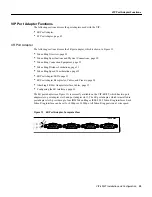
VIP Port Adapter Functions
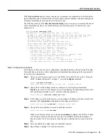
Step 5
To use the configuration you created, enter yes. To discard the configuration file and begin
the configuration process again, enter no.
If you entered yes at the prompt, the following message is displayed:
Press RETURN to get started!
The configuration process is complete. Proceed to the section “Checking the Configuration” on
page 44. It provides show commands you can use to display and verify the configuration
information.
Using the Configure EXEC Command
The configure EXEC command allows you to configure the interfaces for interface processors in the
Cisco 7000 series and Cisco 7500 series. At the privileged command level, enter the ? command to
display a list of privileged level EXEC commands.
To display information about the interface, including the software and hardware versions and the
controller status, use the show controller cbus command. To display statistics about the interfaces,
use the show interfaces command.
Selecting Chassis Slot, Port Adapter, and Serial Interface Port Numbers
The following section describes how to identify chassis slot, port adapter, and serial interface port
numbers.
Note
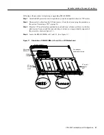
Although the processor slots in the seven-slot Cisco 7000 and 13-slot Cisco 7513 are
vertically oriented and those in the five-slot Cisco 7010 and Cisco 7505 are horizontally oriented, all
models use the same method for slot and port numbering. (For interface processor slot orientation in
your chassis, refer to Figure 2, Figure 3, Figure 4, Figure 5, or Figure 6.)
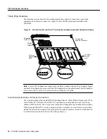
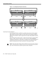
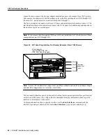
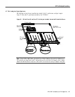
In the router, physical port addresses specify the actual physical location of each interface port on
the router interface processor end. (See Figure 20.) This address is composed of a three-part number
in the format chassis slot number/port adapter number/interface port number.
The first number identifies the chassis slot in which the VIP is installed (as shown in the example
system in Figure 20). The second number identifies the physical port adapter number on the VIP, and
is either 0 or 1. The interface ports on each 4R port adapter are always numbered in sequence as
interface 0 through 3.
Interface ports on the 4R port adapter maintain the same address regardless of whether other
interface processors are installed or removed. However, when you move a VIP to a different slot, the
first number in the address changes to reflect the new slot number.


