


3-2
Cisco UCS S3260 Storage Server Chassis Installation and Service Guide
Chapter 3 Maintaining the System
Status LEDs and Buttons
Front-Panel LEDs
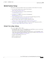
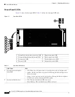
shows the front-panel LEDs.
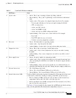
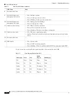
defines the front-panel LED states.
Figure 3-1
Front-Panel LEDs
1
System Power button and power status LED
5
Temperature status LED
2
System unit identification button and LED
6
Power supply status LED
3
System status LED
7
Network link activity LED
4
Fan status LED
8
Internal-drive status LEDs
Table 3-1
Front-Panel LEDs States
LED Name
State
1
System Power button/power
status LED
•
Off—There is no AC power to the system (all power cords are disconnected).
•
Amber—Both server nodes are powered off. Pressing the button will power on
both server nodes.
•
Green—At least one server node is powered on. Pressing the button will power
off both server nodes, returning the LED to amber.
2
System unit identification
•
Off—The unit identification LED is not in use.
•
Blue, blinking—The unit identification LED is activated.
353444
1
2
3
4
5
6
7
1
2
3
4
8


