Supermicro SC213X Series, User Manual
The Supermicro SC213X Series offers high-quality server chassis for optimal performance. Ensure proper installation and maintenance with the included User Manual. Download it for free from manualshive.com to maximize the capabilities of your Supermicro SC213X Series server chassis.
Share
Download


Reviews:
No comments
Related manuals for SC213X Series

PXI-1010
Brand: National Instruments Pages: 63

ION219 Series
Brand: Lantronix Pages: 36

Apollo a6000
Brand: HPE Pages: 9

Apollo 2000 Gen10
Brand: HPE Pages: 86

Apollo k6000
Brand: HPE Pages: 55

RACK-220G
Brand: IEI Technology Pages: 8

SC812L-280U
Brand: Supermicro Pages: 52
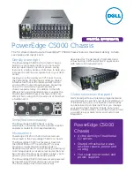
PowerEdge C5000
Brand: Dell Pages: 2

Echo Express SE I Thunderbolt 3 Edition
Brand: Sonnet Pages: 12

5-350D Series
Brand: Hammond Manufacturing Pages: 2

SC113TQ-700CB
Brand: Supermicro Pages: 80

OSD350B
Brand: Optical Systems Design Pages: 12

F1C
Brand: Streacom Pages: 8

BC1
Brand: Streacom Pages: 10

AT-MCR12
Brand: Allied Telesis Pages: 2

AT-SB4151
Brand: Allied Telesis Pages: 11

AT-MCR1
Brand: Allied Telesis Pages: 46

AT-TS24TS
Brand: Allied Telesis Pages: 64


