Cisco T3 Installation Manual Download Page 2

You can install a T3 DFC in any DFC slot of the universal gateway chassis.  


Note 

The Cisco AS5350 and Cisco AS5400 support only one type of WAN DFC at a time. 

Refer to 

"Troubleshooting,"

 for more information.  


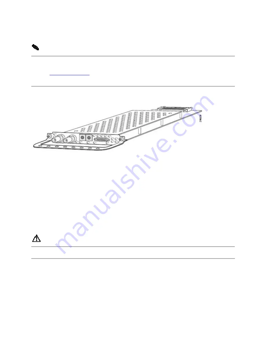
Figure 4-1 T3 Dial Feature Card  


Online Installation and Removal (OIR) of the T3 DFC  

Overview  

To remove a DFC without dropping any calls or connections, you will need to take the DFC out 
of service by using the busyout command to disable the DFC. The 

busyout

 command is 

executed on a per DFC basis and will gracefully disable the card by waiting for the active 
services to terminate.  

If you have active calls on the DFC after executing the 

busyout

 command, wait for the calls to 

drop. Use the show busyout command to view the status of the termination process.  


Caution 

To avoid erroneous failure messages, remove or insert only one DFC at a time.  


When you replace a DFC with a new DFC of the same type in the same slot, the system software 
will recognize the new trunk interfaces and bring them up automatically.  

If you replace the existing DFC with a new DFC of a different type, you will have to reconfigure 
the system. For configuration details, refer to the 

Cisco AS5350 and Cisco AS5400 Universal 

Gateway Software Configuration Guide.


Summary of Contents for T3

Page 1: ... Overview Online Installation and Removal OIR of the T3 DFC Getting Help Where to Go Next Overview The T3 DFC provides physical line termination for a channelized T3 ingress trunk line It uses an onboard multiplexer to multiplex 28 channelized T1 lines into a single channelized T3 line See Figure 4 1 The T3 DFC provides physical line termination for up to 672 DS0 channels and uses onboard HDLC con...

Page 2: ...lly disable the card by waiting for the active services to terminate If you have active calls on the DFC after executing the busyout command wait for the calls to drop Use the show busyout command to view the status of the termination process Caution To avoid erroneous failure messages remove or insert only one DFC at a time When you replace a DFC with a new DFC of the same type in the same slot t...

Page 3: ...igure 4 3 by entering the show chassis command in privileged EXEC mode Router show chassis slot Figure 4 2 Slot Numbering on the Cisco AS5350 Chassis Figure 4 3 Slot Numbering on the Cisco AS5400 Chassis Step 2 Initialize the software busyout procedure by entering the busyout command Router busyout slot number Step 3 Enter the show busyout command to check busyout status for that specific slot ...

Page 4: ...he DFC is offline and ready to be removed Note The OK MAINT LED is green before you enter the busyout command After you enter the busyout command the LED changes to yellow The LED turns off after all calls are disconnected and resources are taken out of service indicating that busyout is complete Step 6 Attach an ESD preventive wrist strap Warning Do not work on the system or connect or disconnect...

Page 5: ...chassis See Figure 4 4 and Figure 4 5 Figure 4 4 Loosen the Captive Screws on the Cisco AS5350 Figure 4 5 Loosen the Captive Screws on the Cisco AS5400 Step 9 Grasp the DFC handle with one hand and pull the card toward you until the card slides free of the chassis Grasp the ventilated metal cover with your other hand to support and guide the DFC out of the slot See Figure 4 6 and Figure 4 7 Cautio...

Page 6: ... remain empty install a blank cover over the open DFC slot to ensure proper airflow inside the chassis See Figure 4 8 Figure 4 8 Blank DFC Cover Installing the T3 DFC Warning Do not work on the system or connect or disconnect cables during periods of lightning activity To see translations of the warnings that appear in this publication refer to the Regulatory Compliance and Safety Information docu...

Page 7: ...figuration Guide To install the T3 DFC follow these steps Step 1 Attach an ESD preventive wrist strap Step 2 Slide the DFC into the slot until the connector pins make contact with the carrier card backplane connector See Figure 4 9 and Figure 4 10 Figure 4 9 Install the T3 DFC in the Cisco AS5350 Figure 4 10 Install the T3 DFC in the Cisco AS5400 Step 3 Align the captive screws with their holes an...

Page 8: ...roubleshooting Getting Help For information about technical support onsite service and exchange and repair services refer to the Obtaining Technical Assistance section on page xii in the Preface Where to Go Next The remaining chapters of this guide include information on installing and troubleshooting DFCs and creating cables Chapter 5 Universal Port Dial Feature Card Troubleshooting ...

Page 9: ... Cabling Specifications ...

Reviews: