


5
Cisco Smart+Connected I/O Extender Reference Guide
OL-27368-01
Rear View (Input and Output Ports)
Rear View (Input and Output Ports)
Connect all applicable devices to the Cisco I/O Extender using the connection options described in the
following figure.
Figure 3
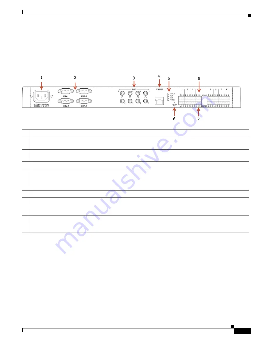
Rear View
1
Power plug port
—AC power receptacle for an IEC 320 power cord.
2
Serial Out
—Four (4) serial output ports for DB9 (receivers, disc changers, etc.).
See the
“Connect the Serial Ports”
section on page 9
for more information.
3
IR Output
—Eight (8) IR output
3.5 mm ports for up to eight (8) IR output transmitters. See the
“Setting Up IR Emitters
or IR Blaster” section on page 9
for more information.
4
Ethernet
—One (1) RJ-45 port for a 10/100 BaseT Ethernet connection.
5
LED Indicators
—Status, Data, Link, Power.
The LEDs on the front and back of the device are the same.
See the
“Front View (LEDs and Other Features)” section on page 4
for details.
6
Reset Button
—
Recessed Reset button. Use the end of a paper clip to press and reset the device.
7
Contacts
(8 sets, Bottom Row)—Pluggable terminal block connectors for eight (8) dry contact closures, logic input
connections, Door Contact Sensors, or Motion Sensors.
Provides power for small devices (12 V), signal input (SIG),
return path (GND). The current, 1250 mA, is shared across all eight (8) sets of contacts.
8
Relays
(8 sets, Top Row)—Pluggable terminal block connector for eight (8) normally closed or normally opened
switchable connections
, such as a blind, a fireplace, or a projector screen. The set contains a connection for Normally
Opened (NO), Normally Closed (NC), and Common (COM). Relays are rated for 24 V 6 A maximum operation.


